So you want to know more…
The module is not just a switch, if you have it in bits you’ll have noticed there is a little more going on and there is that odd disk too…
What seems to be going on here is that there is a little bit more than just mdulating the power to the fan. Rover wanted to avoid sontaneous combustion of the blower motors too. So there are two more parts to this story.
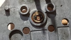
This is a device called a PTC. This is used by the HEVAC ECU to know how hot that heatsink is. Excessive heat can signify a serious failure, a stuck fan or an overload condition. At this point the ECU can kill the drive to the fan. This simply wired between one of the multi plug pins and ground. However it isnt soldered and relys on contact with the heatsink and that spring contact on the board. A bad contact *could* lead the ECU to summise that there is something amiss and shut the fan down. Its certainly worth giving it a clean if you are doing the transistors.
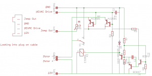
Above is a circuit diagram of the module. Values and compnent names aren’t correct as I just wanted a schematic. I beleive this is correct, although I wouldnt reccomend trying to reproduce it (yet, more later)
The PTC is R1 and as you can see, it simply feeds back to the connector.
The drive transistors are Q1 and Q2. These are in the negative supply to the motor, you’ll also see there is a relay, K1 accross these transistors . You can also see these transistors are in parralel to each other and the failure of one will take out the other.
The drive signal goes right to the transistors but it also goes to the circuitry on the right. When the drive signal reaches a specific value this circuit powers the relay up running the blower at full speed. The reason for this is that there will be a voltage drop over the transistors, even when driven fully on. The relay activates and connects the blower direct to the power supply thus taking this drop out of the circuit. This is the reason that with many of these that fail they will work on full power. Converseley a failure in this circuit or dirty relay contacts could cause loss of full power.
The transistors would normally fail open circuit, in the event they failed short you could end up with a fan jammed on full, however an overload failure would typically annihalate them so it’s unlikeley. The P38’s electrical system does constantly monitor the state of sub compnements so it’s also mot impossible that in the event the blower malfunctions the BECM can kill the aproproate relay (RL6 or RL7)
So what could be done to improve this?
Semiconductor technology has come on a fair way since these were designed. The first job would be to change the transistors to a new type known as a MOSFET. These devices have a much lower voltage drop accross them meaning they generate much, much less heat and place less demands on the driving electronics. It may negate the need for the relay making the whole thing much simpler. Simpler and cooler means a longer life and potentially better system performance. With the lower heat load it’s also possible this could be remade as an external module to save dismantling a faulty blower provided the motor is fine. It may be possible to change the transistors in the module to MOSFETs as it is with minimal changes.


Very informative. Thank you.
Not had the problem…yet
Good to know the route to solve.
What are the Mosfet numbers ?
I’ve not looked at doing it so I can’t give you numbers just yet 🙂