So we now turn our attention to the module.
So time for a little warning here. If you want to follow along or are planning on repairing your module be warned, some of what you are going to have to do cannot be reversed. The module is riveted together and you’ll need a good soldering iron. If you make any mistakes here you could kill the module. Its not a complex bit of kit but you could damage the HEVAC panel.
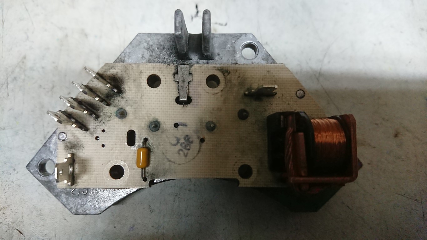
This is the switching module we mentioned in part 1 and takes the place of the resistor pack used in manual systems. The two large metal cans are the transistors used to do the switching and they do fail. Rover used two to split the load over both but one can fail and result in the second failing instantly from overload.
To get in and replace these you’ll need to drill the rivets out from the top (side with the cans). Carfull punch the remains of the rivets out as they hold the PCB on too. You will need to replace these later with bolts.
Flip the board over and desolder the two legs for each transistor. Use a good iron and a solder sucker. Once you get the pins clean the transistors will drop from the heatsink.
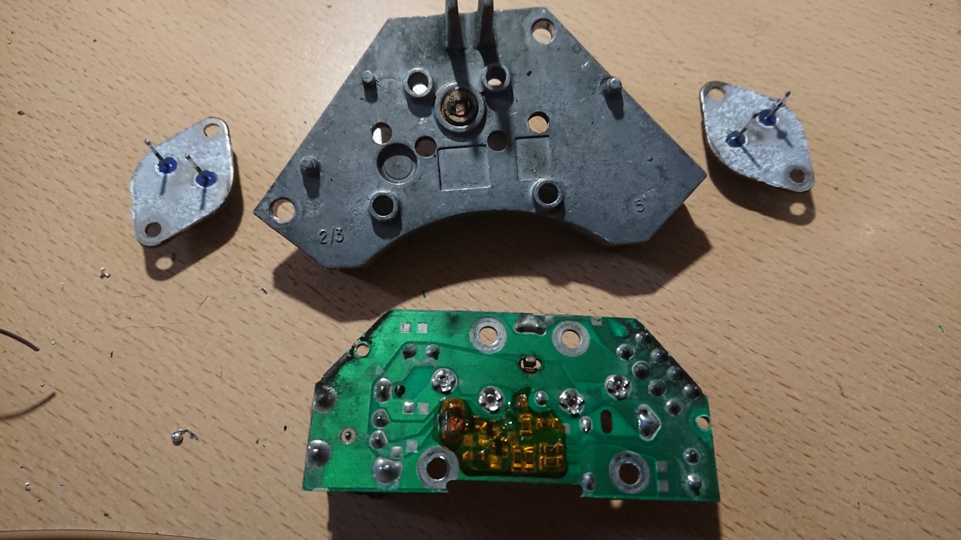
Replacements *can* be found, they are Motorola T1829-1 which are PNP Power Darlington devices. However you’ll be looking at used parts or new old stock, they aren’t easy to find. A drop in replacement is the MJ11015 which is easy enough to find online and from most electronics suppliers. To replace these you’ll need the transistors, heatsink compund and a solvent cleaner. Remove all of the old heatsink compound and gently prize the board off of the heatsink. You should have the following…
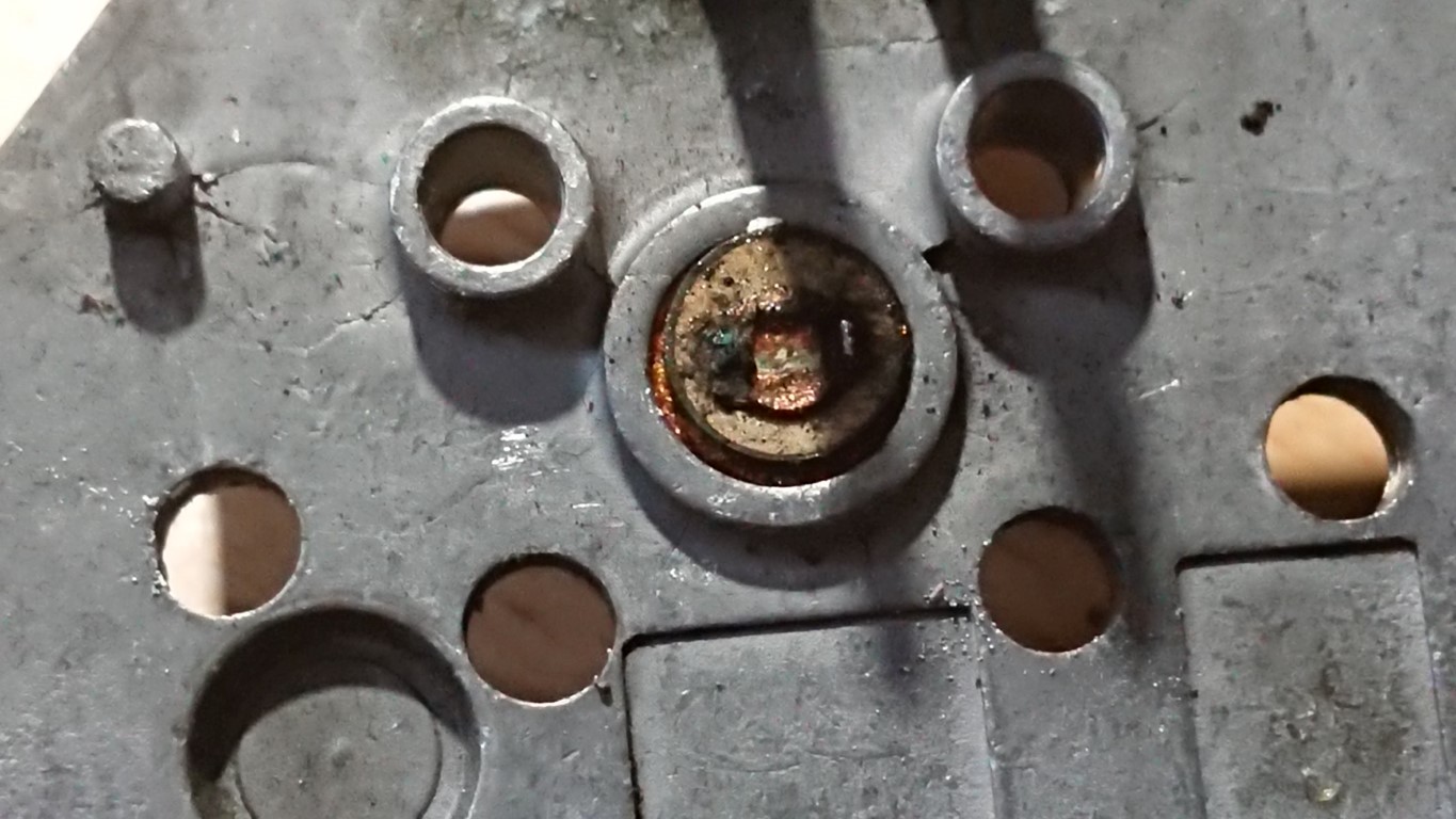
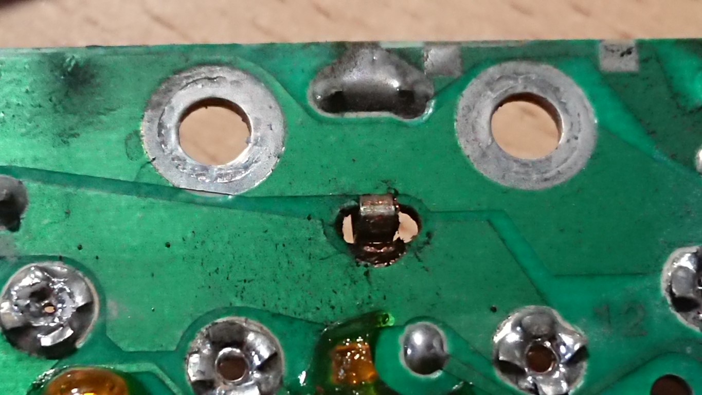
Isopropyl alcohol will shift most of the grot. Treat all the terminals on the board for the connections to the loom and fan to a good clean up with fine emery paper. Make sure that the bottom of the mounting holes for the transistors AND the matching board holes are clean and shiney as these carry the current for the fan motor.
Clip the board back to the heatsink, then apply heatsink paste to the transistors sparingly and a small amount to the mounting area on the heatsink. They will only line up one way and you can guide the pins back through the board. Secure each transistor and the circuit board with M3.5 or M4 bolts and nuts. use shakeproof washers and nylocks to be sure. Using good quality solder, preferably NOT lead free, solder the four pins tow the board and then reassemble the whole module and re-install. With any luck you’ll have a working blower module.
Now, for the curious of you….Lets go down that rabbit holes a little deeper…
Great write up. I found a new resistor block on Ebay with the newer pnp MJ11015. Thought I would try the new resistor. Check it out let me know what you think
HI Richard,
Very informational text. I have a problem with one of my blower motor’s. I am 100% sure it comes from the control module because of you text here. My left blower motor is on Full blow from the moment I put my ignition on one. I have swapped the left with the right motor and then this problem was solved. So I tried to clean the control module with some contact cleaner but with no succes. I do not have the knowledge to do any more than that. But I could find somebody to do it for me although I am pretty sur I will need to state what he needs to do. So my question is. Will my problem be solved if I order these MJ11015 and get them mounted? I have ordered a complete new control module from a citroën Berlingo (french car), because somewhere i had read that they are identical. But once mounted my motor wasn’t running at all. I noticed that on the module the transistors on that one are numbered MJ11016 so 1 diggit difference. Could that lead to a non working motor?
Sorry my English is not very strong. Will I get an email to notify me if you reply on my comment(/question actiualy).
Kind regards!
Sorry I dont check too often. It could well be that the transistor has gone dead short.