Range Rover P38 Blower Module Servicing and Repair – Part 3, How it works, Failure points.

So you want to know more…

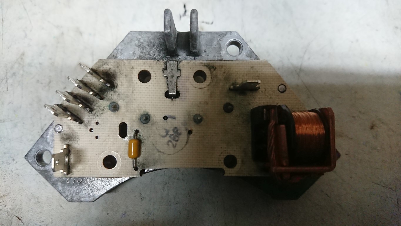
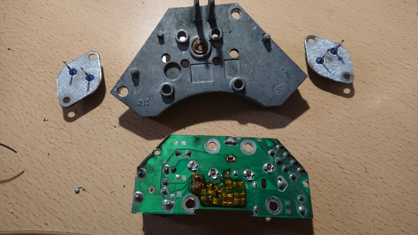
The module is not just a switch, if you have it in bits you’ll have noticed there is a little more going on and there is that odd disk too…

What seems to be going on here is that there is a little bit more than just mdulating the power to the fan. Rover wanted to avoid sontaneous combustion of the blower motors too. So there are two more parts to this story.

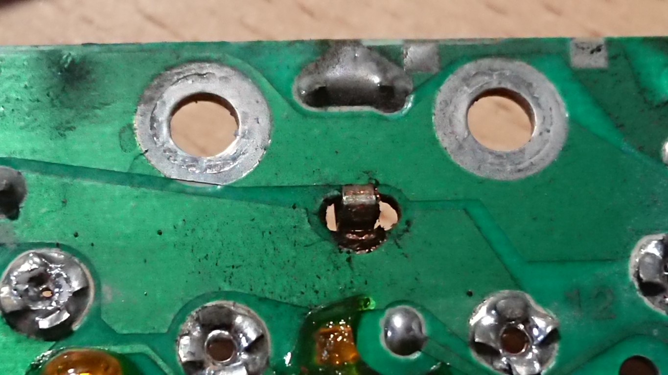
First up is that disk again…

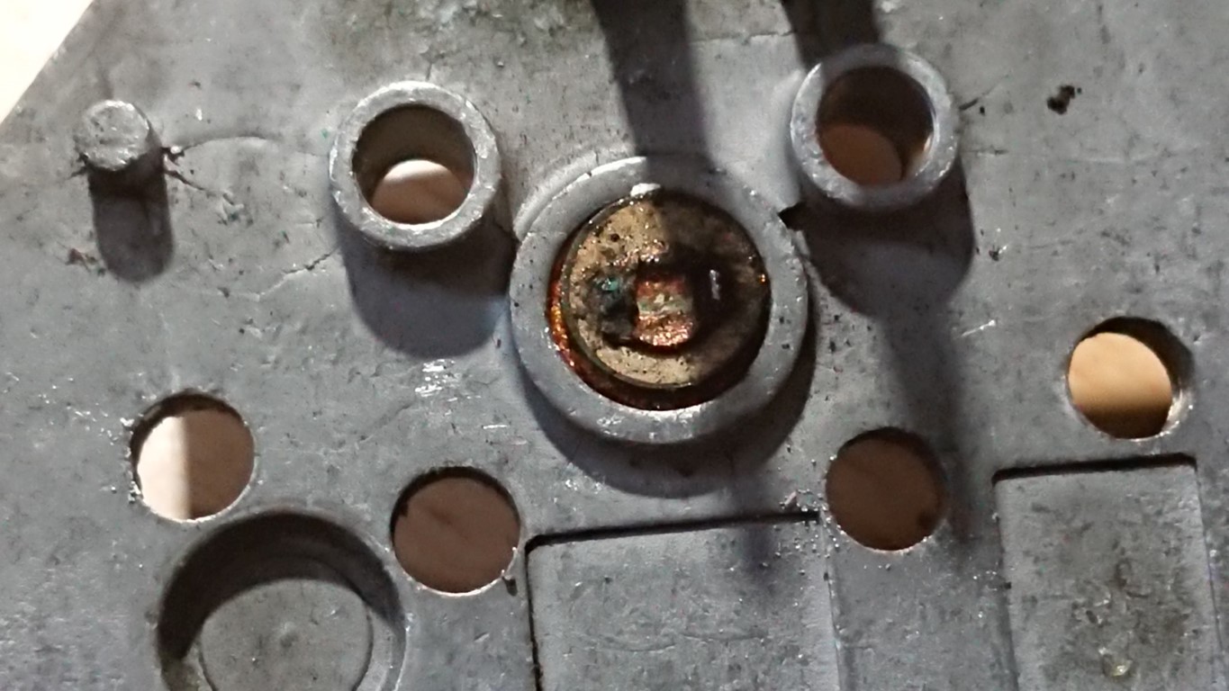
This is a device called a PTC. This is used by the HEVAC ECU to know how hot that heatsink is. Excessive heat can signify a serious failure, a stuck fan or an overload condition. At this point the ECU can kill the drive to the fan. This simply wired between one of the multi plug pins and ground. However it isnt soldered and relys on contact with the heatsink and that spring contact on the board. A bad contact *could* lead the ECU to summise that there is something amiss and shut the fan down. Its certainly worth giving it a clean if you are doing the transistors.

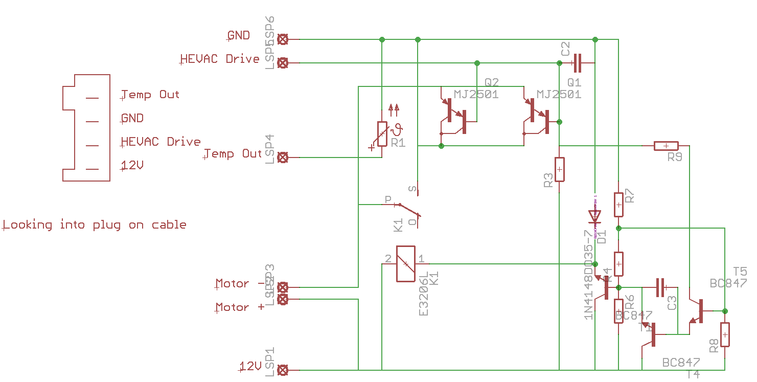
Above is a circuit diagram of the module. Values and compnent names aren’t correct as I just wanted a schematic. I beleive this is correct, although I wouldnt reccomend trying to reproduce it (yet, more later)

The PTC is R1 and as you can see, it simply feeds back to the connector.

The drive transistors are Q1 and Q2. These are in the negative supply to the motor, you’ll also see there is a relay, K1 accross these transistors . You can also see these transistors are in parralel to each other and the failure of one will take out the other.

The drive signal goes right to the transistors but it also goes to the circuitry on the right. When the drive signal reaches a specific value this circuit powers the relay up running the blower at full speed. The reason for this is that there will be a voltage drop over the transistors, even when driven fully on. The relay activates and connects the blower direct to the power supply thus taking this drop out of the circuit. This is the reason that with many of these that fail they will work on full power. Converseley a failure in this circuit or dirty relay contacts could cause loss of full power.

The transistors would normally fail open circuit, in the event they failed short you could end up with a fan jammed on full, however an overload failure would typically annihalate them so it’s unlikeley. The P38’s electrical system does constantly monitor the state of sub compnements so it’s also mot impossible that in the event the blower malfunctions the BECM can kill the aproproate relay (RL6 or RL7)

So what could be done to improve this?

Semiconductor technology has come on a fair way since these were designed. The first job would be to change the transistors to a new type known as a MOSFET. These devices have a much lower voltage drop accross them meaning they generate much, much less heat and place less demands on the driving electronics. It may negate the need for the relay making the whole thing much simpler.  Simpler and cooler means a longer life and potentially better system performance. With the lower heat load it’s also possible this could be remade as an external module to save dismantling a faulty blower provided the motor is fine. It may be possible to change the transistors in the module to MOSFETs as it is with minimal changes.


Range Rover P38 Blower Module Servicing and Repair – Part 2, The control module, dismantling and replacing switching transistors.

So we now turn our attention to the module.

So time for a little warning here. If you want to follow along or are planning on repairing your module be warned, some of what you are going to have to do cannot be reversed. The module is riveted together and you’ll need a good soldering iron. If you make any mistakes here you could kill the module. Its not a complex bit of kit but you could damage the HEVAC panel.

This is the switching module we mentioned in part 1 and takes the place of the resistor pack used in manual systems. The two large metal cans are the transistors used to do the switching and they do fail. Rover used two to split the load over both but one can fail and result in the second failing instantly from overload.

To get in and replace these you’ll need to drill the rivets out from the top (side with the cans). Carfull punch the remains of the rivets out as they hold the PCB on too. You will need to replace these later with bolts.

Flip the board over and desolder the two legs for each transistor. Use a good iron and a solder sucker. Once you get the pins clean the transistors will drop from the heatsink.

Replacements *can* be found, they are Motorola T1829-1 which are PNP Power Darlington devices. However you’ll be looking at used parts or new old stock, they aren’t easy to find. A drop in replacement is the MJ11015 which is easy enough to find online and from most electronics suppliers. To replace these you’ll need the transistors, heatsink compund and a solvent cleaner. Remove all of the old heatsink compound and gently prize the board off of the heatsink. You should have the following…

There is a small disk set in between the transistors that *may* drop out if you arent careful. clean everything off especially the contact for the small disk..

Isopropyl alcohol will shift most of the grot.  Treat all the terminals on the board for the connections to the loom and fan to a good clean up with fine emery paper. Make sure that the bottom of the mounting holes for the transistors AND the matching board holes are clean and shiney as these carry the current for the fan motor.
Clip the board back to the heatsink, then apply heatsink paste to the transistors sparingly and a small amount to the mounting area on the heatsink. They will only line up one way and you can guide the pins back through the board. Secure each transistor and the circuit board with M3.5 or M4 bolts and nuts. use shakeproof washers and nylocks to be sure. Using good quality solder, preferably NOT lead free, solder the four pins tow the board and then reassemble the whole module and re-install. With any luck you’ll have a working blower module.

Now, for the curious of you….Lets go down that rabbit holes a little deeper…


Range Rover P38 Blower Module Servicing and Repair – Part 1, Theory, Teardown and Motor Check.

Anyone who knows these cars and is trying to keep one on the road will sooner or later run into HEVAC problems. These seem to stem from the blend motors or the blower modules as a rule. As I have a spare one and a dead one on the car I decided to take the spare and totally overhaul it and try and see what actually fails on these as well as document how they work.

As with a number of modern cars these modules aren’t simply motors but contain some electronics too. Having dug deep in these Rover did some good work but were possibly constrained by what they had to work with, this seems to be the source of the issues.

Simpler cars simply use a multi position switch to feed a series of power resistors, these give you your different fan speeds. These resisters can and do fail, as do the switches and this can cause loss of speed settings, the whole fan and in some cases (Looking at you here Vauxhall) spontaneous combustion of the air box.

When you are looking at a climate control system you need to control the speed of the fan via a computer of some sort, switching relays and transistors can be done to use the resistor system but its simpler and more precise to use something called PWM. Here instead of a simple on/off signal we use a transistor as a switch to control the power to the motor. If we then switch the transistor quickly you can control the speed of the motor by how long the signal stays on. At a basic level you now have 255 speed settings vs 4 or 5 and the computer in the HEVAC can manage it electronically.

Most systems them mount the switching transistors on the motor assembly. Modern cars use the same system for engine fans and all sorts of other systems. You supply the fan with power and a switching signal and everything is normally cooled by the fan too. All the big heater resistors are redundant and controlling two fans for dual zone climate control as the P38 uses is much easier. It means there’s no heavy duty switching going on in the ECU (HEVAC Panel) so that can be smaller and integrated with the controls.

Now, The P38 system was advanced at the time but they did make some curious design decisions and were limited by the parts they had to use. A lot of P38 electrical gremlins come from the same source, bleeding edge design that was close to what was practical at the time.

So, lets tear into it…

Either blower comes out easy enough. The procedure is covered elsewhere and I won’t go into it. It does work a little easier on the V8 if you drop the Cruise relay and the ECU that’s with it off the bracket. You get more space.

Once its out, pull the red and black motor connections from the electronics module. Looking at the side you’ll find three rectangular holes spaced equidistantly round the side. Push a flat screwdriver into each hole and gently pull the motor and fan assembly up out of the plastic. You’ll have to work around all three a few times but it will eventually prize out and you can guide the grommet and wiring through the plastic. Put the motor aside as we will look at this first, make sure the little rubber mounts do go astray. 3 screws hold the electronics to the plastic and the aluminum module can be withdrawn. You should have something like this now…

There are a few known issues. The most common is a simply dead unit, in which case you *could* likely swap just the electronics from a known good unit and snap it all back together. However I feel there may be other things at play here.

Another known issue is for the blower motors to torch the fuse box. The most commonly posited reason for this is blocked pollen filters, however with no air to circulate the load on the fan should be less, not more, so this explanation makes little sense. However stripping my unit I spotted something else, the motor was not free to move, well not as free as it should be. Powering the fan up from a bench power supply put the supply into protection at a current way above what I expected, Ah-Ha! So first job was to degunk, clean and lubricate the bearings. The top one is easy enough to do, the bottom one, less so. The motor cannot be stripped any further so its a case of the best you can do. Light machine oil was used on the bearings and some graphite grease to lube the brushes. The motor now not only span easier but drew significantly less current and was quieter. I would pin the fuse box burn outs on stiff motors before filters. As the whole lot comes apart easy enough this is a simple job to do “just in case”

On to the electronics….