Category Archives: Uncategorised

Hacking the Audi Concert Pt 2 – Front panel, Keypad

SO into deep hack. I want to be able to talk to the front display and buttons. Although I plan to replace the deck this doesnt give me all the buttons I might want. A quick poke shows that I get 3 buttons to work with if I pick the deck commands up as is. I’d like more and I’d also like the front panel to say something other than ‘TAPE’

The Concert and Chorus are more or less the same thing so the manual here covers both. A quick look shows us we want X1001 (The front panel connector) and in particular pins 2, 3 and 4. These compose the SPI interface to the panel. With my analyser set for Active low clock, validon  leading edge and enable (status) active high I’m able to see whats going on.

Now I’ve only been looking at these three lines and something that is imediately of concern is that the schematis shows these as unidirectional TO the display. I beleive this to be an error.  Status is shown as originating from the display, again, I’m not sure on this one.

Watching the exchange its imediately clear that there is a simple command set in use here. The first byte seems to specify if the data of coming from the keypad or to the display. The keypad is pretty simple.

The first byte is always 0x25 followed by a key ID. A key up is sent when a key is released (0x21).

The keycodes apear to be:

0x01 – 1
0x02 – 2
0x03 – 3
0x04 – 4
0x05 – 5
0x06 – 6
0x07 – Seek >
0x08 – TP
0x09 – RDS
0x0A – CPS
0x0B – MODE
0x0C – <<
0x0D – FAD
0x0E – BAL
0x10 – BASS
0x11 – AM
0x12 – Dolby
0x13 – >>
0x14 – TREB
0x15 – AS
0x16 – SCAN
0x17 – FM
0x18 – Seek <
0x19 – REV
0x1A – Knob +
0x1B – Knob –
0x1E – Code in (TP+RDS)

There may be others but this seems to cover most. Interestingly the controller is pretty dumb, switching to tap or CD doesnt diable the unused button, the micro on the board just ignores it. This means intercepting these unuded keys should be trivial enough giving full use of ALL buttons.

On boot the keypad does send 0x25, 0x00 which seems to be a message stating that no keys are down at boot. I’ll verify this.

So in summary for the keypad, this all looks very simple to get to. I could now simply drop into tape mode as per the original firmware and be done but as I plan to have both bluetooth and MP3 built I’d like more functionality and that means the display.

So, on to the display…

Hacking the Audi Concert

My latest aquisition is an Audi A6 2.8 Quattro. Of the many really nice bits of thought that Audi put into this was the flap that covers the head unit. Like many I like as little light in the cabin as possible as night so I thought this was great. Sadly the Alpine head unit, which is Awesome) that has been fitted after market sticks out too far, you cant close tha flap. In fact a quickl look shows that most manufacturers insist in a stupid, huge control knob, so there is nothing that will drop in. I’d also like to keep is stock and get the dash display back. So off we go looking….

Exhibit 1, the Concert 2. This is CD rather than Casette but requires a CAN bus equipped car. The facelist A6 B5 does support this and this is the radio in those cars. It supports the BOSE audio system in mine, should make the dash work and supports multiple inputs (CD Changer, Nav, Phone) So should be hackable for bluetooth and Line in. I obtained a CAN adaptor and off we went…..

No Dash screen. Seems the Concert 2 wants to chat to the dash screen over CAN, not the FIS interface my car had. Bugger. This is fixable with a different CAN adaptor to the one I have. It shouldnt be a huge thing to make a convertor. A bigger pain is despite being the radio fitted in the facelift car it physically doesnt fit. You have to press both controls in and then close the flap which will turn the radio back on as it presses the tops or turns it off. Close but no cigar.

So Option 2. Hack a concert. Having otained one I hit the first big snag. Unless you have the code you are stuffed. Working concerts with the code and working volume controls are few and far between.  I’ve stripped it down and decided there are a few ways to do this but by far the easiest is the realisation taht the tape unit is not only a module but its largeley independant with its own MechCon board. As this is a logic driven deck its very likeley this board simply takes commands from the main MCU in the form of play/stop/rev/etc. Having found a schematis the audio out from the head pre-amp is easy to get to as well so a drop in board is a possiblilty.

The MCU uses a large number of serial busses which are a mix of SPI, I2C and RS232 and each section of the radio is a clearly defined block so there are a large number of possibilities here.

First goal is to get this bugger unlocked. I have the dev kit for the Micro they chose (Its been in storage for years because I thought it may be useful) so I’m planning on sucking its brains out and pulling the code out. I’m also chasing Audi who, in the manual, insist its a free service but the main stealers want £50 to get the code.  Audi UK are chasing this for me. Given that locked ones can be found easilly it may be a better bet to work out how to get it myself.

http://kovo-blog.blogspot.co.uk/2015/08/audi-chorus-concert-how-to-recover.html

Gives some pointers on how to do it, so I guess this is the first stop. I modified a cheap CH340 dongle and using that circuit pulled the code out first time. Not only can you do this WITHOUT removing the micro Audi/Blaupunkt left test pads for all of these connections under the board…

Concert EEPRON recovery
Concert EEPROM recovery

Its worth noting at this point that it *should* be possible to suck the ROM contents out too. I’m not sure if this version of the chip uses EEPROM or Mask ROM/EPROM for the main program. Armed with a disassembler it should be possible to fix the actual bug. You can also use the MotoHack tool to change the keycode or disable it. I opted to leave well alone as I dont know if there is a checksum in there or not.

Having pulled the cod I confirmed it does work and unlocked the unit. Turns out my display is a little dead but for our purposes its good enough. Off we go now to decipher the front panel…

Next: Keypad Hacking

Getting a Terrafix Vehicle PC up and running.

<><><><><><> WORK IN PROGRESS <><><><><><><>

CPU: AMD Geode LX MMX @ 500MHz (K6 Core)
RAM: 512Mb DDR 333 PC2700
IDE/SATA: VIA VT6241
Audio: Realtek ALC206
Video: AMD Onboard Geode Lx800
GPS: UBLOX Serial
3G: Unknown GPRS
Serial: 2x on board UART on Kontron ETX-LX which dont seem to be used.  8x Exar XR17V158

In theory there are 6 devices available externally. On top of that the GPS, 3G and Touchscreen need AT LEAST one serial port each. The driver for the serial multiport card will start assigning from the next available com port BUT it seems like the order is preserved. EG if it starts at COM5, Com5 is the first port. Same if it starts at COM6 etc.

Ublox TIM-4H GPS Receiver
Seimens HC15 GSM/UMTS/HSDPA Modem

I managed to grab one of these for  good money a few weeks ago. I’m not sure what it’ll get used for but it seemed like a good idea to see if Tezero would be ok on it.

First up this one had no cables, no drive or drive mounts. This is the first challenge.

Although it uses a dual link DVI connector dont be fooled. This connector is a custom LVDS connection, you need to use the supplied monitor. There is an SVGA connector under the board but I dont have the pinouts for this. Finding them will mean dragging the scope out and I wanted to avoid this. Once again, its a DUAL link digital cable. Using a single link or analog cable wont work. Using a DVI monitor will also, not work. Assuming that the LVDS connections are directly driving this port you might even kill the LVDS drivers trying. I didnt but I may have been lucky.

20151126_110058
This is a single link DVI cable, it’ll power up the monitor but it wont work!
20151126_110111
This is the one you need, known as a dual link cable

Next is the power connector. This is a standard 4 pin molex as per the PC 12Aux connector from an ATX PSU. I’ll pop the pinouts up in a lil while. A word here, these things are very picky about supply voltage. If you supply under 12V they wont even try and power up.
20151126_110150
The pinouts as far as I’ve been able to discover.

This is all you need to get it powered up. The ? pin goes to an optocoupler and I suspect is for the brake/handbrake input. Pin 1 must be pulled up to +12v to get the unit to power on. If it is allowed to go low the unit will shut off after a second or two. There is no load on this pin as this is all carried by pin3. This is used to charge the internal pack and run the unit. A 5A fuse in this line would be good. The PSU *MUST* provide a good quality output, I had a LOT of issues getting going and it turns out it was mostly down to PSU issues, I was using an ATX PSU and the +12V was ocasionally wandering down as low as 11.4V which was enough to upset the unit.

20151126_110206
I reused an ATX Aux12V connector to get running. Realise if you do this that the colour codes are totally and utterly wrong!

Internally you have a plethora of hard drive options, however here you’ll hit the fist real snag. The SATA headers will recognise an optical drive, but they wont boot from it. The IDE header is also 2.5″ IDE so unless you have an adaptor cable thats not going to happen either.

You’ll need a 2 pin molex minifit to get +5v power for your drive if you are going the SATA route, in my case I’ve used a 32Gb Team SSD. You could eaqually use a CF card. Soldering in a SATA power connector is an option as below. However this will ONLY work with Laptop drives that only use +5V

20151126_113326

Now, there is a SATA connector on the Terrafix board, the aforementioned 2.5″ IDE header and a CF slot. There is also a CF slot on the CPU card and two SATA ports. The CF card slots are bootable as are the SATA ports, although the ones on the CPU card seem more reliable. USB Booting does not work, network booting definately does.

The CPU on here is an AMD Geode at 500MHz, so realistically with the 512Mb of ram you are looking at Linux or XP. 7 *might* boot but based on experiences with Atom based machines, it wont be much use. If going the XP route then look at XP Embedded. its still supported and is undoubtedly the way Terrafix went. A low footprint Linux install would work too.

Setup Time
Heres the good news. Windows 7 PE wont work. Win XP PE *might* but I have no means to test it. Bootable USB media doesnt work and booting off the IDE header seems to, there is another BUT here. You are going to need the VIA VT6421 drivers. You can either slipstream these in with nLite OR if you can find a USB floppy drive and a disk, do it that way. If you are going the Linux route I have tested Debian and it went on with no real issues. I have made an image with nLite thats missing a lot of the cruft and is tweaked specifically for this sort of application however you will need an XP Pro licence key and you need to bear in mind XP is discontinued. I may upload this later.
If you have a 2.5″ to 3.5″ adaptor its not all plain sailing, it seems that the header they have used is a bit too narrow for a standard laptop IDE header, I had to shave the edges of mine down a little with a scalpel. I pulled +12V off of the PSU I was using and picked +5V up off of the IDE cable. A good ground is important too, dont rely on the ribbon.

20151126_115502

Alternatively you should be able to use a USB drive, the BIOS supports USB CD-ROM, Win XP will setup fine from one however I only have a DVD drive which it doesnt seem to like. You’ll need a powered drive too as the power output of the USB ports is pretty low.

You *could* in theory use another machine, do the OS install on there and move it over, however you are going to hit the same driver issues when you move it over. Unless you have something with a VT6421 controller in (Its an OLD chip) this is probobly not the best way.

There is also provision for a reset button which may be handy while setting up. Simply short the pins.

20151126_120628

I had issues with corrupt didsk, lockups and all manner of silliness, this all seems to have been caused by a combination of PSU issues as above and a bad stick of ram.

All the drivers are available. I’ll likewise pop these somewhere however there seems to be an issue with the multi port serial and possibly the modem too. This could be the bit that causes issues.

Not one of the serial ports seems to do anything, in addition the modem must be powered on. if it is or not, there’s no way to tell but I suspect there is some funky stuff going on with the Altera CPLD under the processor board. it may be there is an inhibit line there that needs tweaking. For now I need to get the scope out and see what comes out of the UART and where it goes.


When will we learn?

So the IoD have called for more government action in the shadow of the TalkTalk hacks.

Let’s look at this quickly. IT security is a necessary evil nowadays, not matter how big or small you are you WILL be attacked. As an example while setting up an Asterisk system for our Canada office it was very briefly open to the world. It took less than 5 minutes for it to be attacked (unsuccessfully) however let’s put that into perspective…

There are at last guess, 3,706,452,992 public facing IP addresses out there. Yet in 5 minutes a number of people noted and attacked just one. If you take the assumption that seems to be the norm with many directors that there are a small group of hackers in their bedrooms then the odds of hitting our server are similar to hitting the lottery. This points to a more likely and well known scenario in the security community, that this is a major form of organised crime.

Now with such a vast address space it suddenly makes no sense from an economic point to concentrate all your resources on one single host. In fact it’s easier to scan and pick on the low hanging fruit. The misconfigured, poorly maintained badly written sites and those relying on security through obscurity. And here we come to the crux of it.

As a director you are responsible for your business. You make sure your premises are secure, you make sure all your staff are safe and you protect your business. And yet for many businesses, especially larger ones, IT is simply something you must have and the trick is to spend as little money on it as possible. Your IT provider is responsible for your security online and making sure your internet presence is as safe as your real work presence. When this department is typically starved of resources, contracted to the lowest bidder with no check of their credentials, or outsourced, things can and do go wrong.  You wouldn’t go to B&Q and put £5 locks on all your doors, but for most the ISP’s supplied free router, and a £5 a month hosting package are ‘good enough’.

And Talk Talk? It’s looking like it was an SQL Injection attack, the kind that every IT professional knows about, knows the risks and knows to NEVER allow out into the wild. If this was the cause of the leak TalkTalk should be sued into oblivion and its directors jailed. It’s inconceivable that a company so big dealing with so much data should fall prey to such a basic flaw.

So no, IoD, we don’t need more government help. We need you to give your members a BIG wake up call. IT has been starved and treated as something you have to have but spend as little as possible on for too long, so much that it’s become institutionalised. This needs to change, or more of your members will fall the same way. This is a problem your members have caused and they alone can fix.

If government help is needed its to make this behaviour on behalf of company directors a criminal offence with strong punishments to include custodial sentences and large fines. Stop starving IT of resources from being a viable cost cutting measure.

Realtek Support in ESXI 6

This is more a note for me. I’m always forgetting this. Most motherboards use a Realtek chip so the following will get it going in most cases. You are going to need to reboot so make sure all clients are stopped.

Grab https://vibsdepot.v-front.de/depot/bundles/net55-r8168-8.039.01-napi-offline_bundle.zip

Pop it in your datastore, in my case it goes (with other bits I need) in the first datastore, eg the default one called datastore1.

Enable SSH server in BOTH services and firewall, configureation -=> security profile. If you plan on using SSH after this make sure that you set SSH server to ‘Start with host’ else it’ll be gone when you reboot.

SSH into the server

esxcli software acceptance set –level=CommunitySupported

esxcli software vib install -d /vmfs/volumes/datastore1/scratch/net55-r8168-8.039.01-napi-offline_bundle.zip

reboot

Once the server reboots your NIC should show.

Mitel 5235, FreePBX and PFSense

These phones are popping up cheaply all over the show. For the money these go for you are getting a lot of phone, however thos buying them and expecting them to just work you will have issues.

This guide will get you up and running AND get the BLF working with the above systems. The information eaqually applies to any Asterisk and Any DHCPD.

To be fair the asterisk side of things is easy, make an account and if you want to use BLF make sure the hints you need are setup. This is covered in many articles. Make a SIP account for the phone and note the details down.

Now you’ll need a working TFTP server. This is usually your FreePBX box so we will work with that assumption. In the root you need the phones firmware (Google will find this easilly). And a number of other files which come with the firmware. You will also want to create a file called MN_Generic.cfg. This will contain all the default settings for all your phones, things that wont change from phone to phone. Feel free to use the one at the end of the article. There are a lot of examples kicking about.

Finally, the per phone data. You can do this two ways. Using a file called MN_<MAC>.cfg will tie the final configuration details to THAT phone. This means that when the phones get to their destination the right phone must go in the right place. If you are doing the final setup now this may be your best bet. Remeber that is a phone dies, you’ll need to rename this file.  The alternative is to use MN_<userid>.cfg. In this case the phone will boot and ask for a user ID. When the user enters their ID the matching .cfg is loaded and the phone reboots with these settings. This is handy if you arent doing the final config. You can ship all phones in the basic setup state and the end user puts the phones wherever and THEN sets the config up. You can also use this to allow users to move between phones. The manual for the phone shows how this works.

Either way you need to create one of the above files. You can add as much or as little as you want. Bare boes it should contain:

<Parameter Model=”5235″>
<user_list>
<User State=”1″ ID=”<ID>” DispName=”<USERNAME>” Pwd=”<PASS>” AuthName=”1008″ Realm=”” RegSvr=”<FREEPBXIP>” RegPort=”5060″ RegScheme=”2″ ProxySvr=”<FREEPBXIP>” ProxyPort=”5060″ ProxyScheme=”2″ VMSvr=”<FREEPBXIP>” VMPort=”5060″ VMScheme=”2″ OutSvr=”” OutPort=”5060″ OutCtr=”0″ Ring=”1″ Line=”0″ EventSvr=”” EventPort=”5060″ EventScheme=”2″ NatMode=”0″ NatType=”option” NatIp=”0″ BlfGroup=””></User>
</user_list>
</Parameter>

Set <ID>, <FREEPBXIP>, <USERNAME> and <PASS> accordingly. <USERNAME> Is displayed by the phone on the LCD  and not used elsewhere. Save this with one of the above.

Right, here we go, reboot or power on the phone.

Setting up the phone:
This is a bit different. You’ll need to use a POE injector and know the phone is in SIP mode. Once you have power disconnect the phone and press the * key and power up holding it down till the phone does something. If you see ‘Erasing PIN’ then the phone needs resetting to SIP. Pull the power out and press * and 7, keep them held down. When asked if you want to revert to sip mode press * for yes and reboot.

Once the phone reboots you’ll likeley see it rejecting DHCP offers, you thought this was simple. You have two choices here. Booting with * held now you can manually set the TFTP server under ‘Modify Static Parameters’. To do it via DHCP you need to add some custom options. In PFSense go to the GUI, go to Service-=> DHCP Server and scroll down to ‘Additional Boot/DHCP Options and click the button. Click the add button. Now we need to add a string, for number 128. The string needs to be of type Host or IP Address and point it to your TFTP server. The same needs to be done for 129, although we arent using it the phone will complain and sulk if it’s not given. The same goes for 130 which should be set to MITEL IP PHONE and is a text field.

Reboot the phone it’ll complain, reboot and then download SIP firmware. It may complain and reboot once or twice but it’ll get there. Once its booted it’ll walk you through some setup steps and log in.  If you are working per user at this point it’ll be asking for a user id. This is why you created the MN_xxxx.cfg file. Enter a user id that has a matching file, eg MN_1000.cfg would be 1000. Click the Submit button on the screen. If you went the MAC route it may reboot again and then you should be up and running.

The only real issues hit here with that is if the phone has not been factory reset it can behave a little oddly, normally things like the built in HTTP server fail. Booting the phone with * held down will get you to the boot menu and you can do a factory restore in there. All PINs/Passwords default to 5235 and the web login defaults to admin/5235. These can be overridden in the config file.

<Parameter Model=”5235″>
<dhcpenable>1</dhcpenable>
<tftp_config>1</tftp_config>
<pppoe_enable>0</pppoe_enable>
<tftp_task_enable>1</tftp_task_enable>
<boot_version>02.01.00.05</boot_version>
<image_version>R8.0.08.00.00.04</image_version>
<tftp_upgrade>0</tftp_upgrade>
<http_upgrade>0</http_upgrade>
<outbound_state>0</outbound_state>
<local_sip_port>5060</local_sip_port>
<tls_port>5061</tls_port>
<tos>0</tos>
<e802_priority>-1</e802_priority>
<vlan_id>-1</vlan_id>
<host_name>MN08000F1C071B</host_name>
<domain>-example.com</domain>
<addr_type>0</addr_type>
<hot_line>0</hot_line>
<hot_address>operator@example.com</hot_address>
<hot_addr_type>0</hot_addr_type>
<tls_private_url></tls_private_url>
<tls_certificate_url></tls_certificate_url>
<tls_ca_cert_url></tls_ca_cert_url>
<tls_root_cert_url></tls_root_cert_url>
<tls_certificate></tls_certificate>
<tls_ca_cert></tls_ca_cert>
<tls_root_cert></tls_root_cert>
<poundkeydial>1</poundkeydial>
<dialtonekey>12</dialtonekey>
<htmlpuseraccess>1</htmlpuseraccess>
<remote_reboot>1</remote_reboot>
<checkpeercert>0</checkpeercert>
<sipkeepalive>1</sipkeepalive>
<rss_feed>http://open.live.bbc.co.uk/weather/feeds/en/2637487/3dayforecast.rss</rss_feed>
<blf_pickup>*8</blf_pickup>
<host_ip>135.199.77.12</host_ip>
<video_ip>135.199.77.12</video_ip>
<sntp>pool.ntp.org</sntp>
<time_zone>0</time_zone>
<auth_method>2</auth_method>
<register_expire>7200</register_expire>
<session_timer>1800</session_timer>
<emerg_number></emerg_number>
<emerg_ip>0.0.0.0</emerg_ip>
<emerg_port>5060</emerg_port>
<audio_codec>5</audio_codec>
<audio_pkt_size>20</audio_pkt_size>
<video_codec>0</video_codec>
<dtmf_type>0</dtmf_type>
<dtmf_payload>101</dtmf_payload>
<advisorymsg>0</advisorymsg>
<reasons>0</reasons>
<other_reason></other_reason>
<do_not_disturb>0</do_not_disturb>
<noans_fwd_mode>0</noans_fwd_mode>
<try_ring_nums>10</try_ring_nums>
<noans_fwd_addr></noans_fwd_addr>
<beep_on_hold>1</beep_on_hold>
<on_hold_alert>60</on_hold_alert>
<system_mode>0</system_mode>
<pppoe_login></pppoe_login>
<pppoe_passwd>******</pppoe_passwd>
<callCountIn>0</callCountIn>
<callCountOut>1</callCountOut>
<discovery>0</discovery>
<pbIndex>0</pbIndex>
<adminId>admin</adminId>
<admin_dispname>Administrator</admin_dispname>
<admin_passwd>923e325e16617477e457f6a468a2d6df</admin_passwd>
<busy_fwd_mode>0</busy_fwd_mode>
<busy_fwd_addr></busy_fwd_addr>
<always_fwd_mode>0</always_fwd_mode>
<always_fwd_addr></always_fwd_addr>
<pcport>0</pcport>
<lanport>0</lanport>
<lcd>14</lcd>
<lcd_brightness>9</lcd_brightness>
<rdkw1></rdkw1>
<rdringtype1>0</rdringtype1>
<rdvmail1>0</rdvmail1>
<rdblock1>0</rdblock1>
<rdkw2></rdkw2>
<rdringtype2>0</rdringtype2>
<rdvmail2>0</rdvmail2>
<rdblock2>0</rdblock2>
<rdkw3></rdkw3>
<rdringtype3>0</rdringtype3>
<rdvmail3>0</rdvmail3>
<rdblock3>0</rdblock3>
<rdkw4></rdkw4>
<rdringtype4>0</rdringtype4>
<rdvmail4>0</rdvmail4>
<rdblock4>0</rdblock4>
<rdkw5></rdkw5>
<rdringtype5>0</rdringtype5>
<rdvmail5>0</rdvmail5>
<rdblock5>0</rdblock5>
<dtringtype1>0</dtringtype1>
<dtringtype2>0</dtringtype2>
<dtringtype3>0</dtringtype3>
<dtringtype4>0</dtringtype4>
<dtringtype5>0</dtringtype5>
<dtringtype6>0</dtringtype6>
<dtringtype7>0</dtringtype7>
<dtringtype8>0</dtringtype8>
<dtringtype9>0</dtringtype9>
<dtringtype10>0</dtringtype10>
<dtringtype11>0</dtringtype11>
<dtringtype12>0</dtringtype12>
<http_task_enable>1</http_task_enable>
<https_task_enable>1</https_task_enable>
<httpport>80</httpport>
<httpsport>443</httpsport>
<telnet_task_enable>1</telnet_task_enable>
<voicemail_ringnum>4</voicemail_ringnum>
<gruu_ctl>1</gruu_ctl>
<proxyrequire_ctl>0</proxyrequire_ctl>
<fwEnable>0</fwEnable>
<fwWanurl></fwWanurl>
<sym_udp>0</sym_udp>
<stunip></stunip>
<fwWanDurl></fwWanDurl>
<fwMode>0</fwMode>
<start_port>20000</start_port>
<end_port>20998</end_port>
<multi_user_enable>0</multi_user_enable>
<upgrade>0</upgrade>
<bksrvtm>3</bksrvtm>
<ntfcfg>0</ntfcfg>
<lancode>en_GB</lancode>
<tonecode>GB</tonecode>
<dsmode>1</dsmode>
<dsmonth>3</dsmonth>
<dsweek>2</dsweek>
<dsday>1</dsday>
<dsemonth>11</dsemonth>
<dseweek>1</dseweek>
<dseday>1</dseday>
<ds_transition_time>2</ds_transition_time>
<flashVer>201</flashVer>
<http_download>sipdnld.mitel.com</http_download>
<tftp>192.168.99.7</tftp>
<downloadtype>1</downloadtype>
<dialpl></dialpl>
<gtEnable>0</gtEnable>
<dtimer>3</dtimer>
<autoanswer>0</autoanswer>
<ringPitch>0</ringPitch>
<keysys_enable>0</keysys_enable>
<pbName1>My Number</pbName1>
<pbaddr1>*65</pbaddr1>
<snmp>0</snmp>
<srtp>0</srtp>
<pkDescription>
<Key Line=”25″ Fea=”6″ Des=”Line  1″ Addr=”” Addr2=”” Mode=”1″ Mode2=”1″ UserID=”1005″></Key>
<Key Line=”26″ Fea=”7″ Des=”Line 2″ Addr=”” Addr2=”” Mode=”1″ Mode2=”1″ UserID=”1005″></Key>
<Key Line=”27″ Fea=”2″ Des=”Call Logs” Addr=”” Addr2=”” Mode=”1″ Mode2=”1″ UserID=””></Key>
<Key Line=”28″ Fea=”3″ Des=”Advisory            ” Addr=”” Addr2=”” Mode=”1″ Mode2=”1″ UserID=””></Key>
<Key Line=”29″ Fea=”4″ Des=”Headset             ” Addr=”” Addr2=”” Mode=”1″ Mode2=”1″ UserID=””></Key>
<Key Line=”30″ Fea=”19″ Des=”Weather” Addr=”http://open.live.bbc.co.uk/weather/feeds/en/2637487/3dayforecast.rss” Addr2=”” Mode=”1″ Mode2=”1″ UserID=””></Key>
<Key Line=”31″ Fea=”19″ Des=”Currency” Addr=”http://www.xe.com/rss.xml” Addr2=”” Mode=”0″ Mode2=”1″ UserID=””></Key>
<Key Line=”32″ Fea=”19″ Des=”News” Addr=”http://feeds.bbci.co.uk/news/rss.xml?edition=uk” Addr2=”” Mode=”0″ Mode2=”1″ UserID=””></Key>
</pkDescription>
<webdialurl></webdialurl>
<cw_tone>1</cw_tone>
<missedcallsctl>1</missedcallsctl>
<callforwardctl>1</callforwardctl>
<lcdbacklightctl>1</lcdbacklightctl>
<time_format>1</time_format>
<csta_enable>0</csta_enable>
<csta_passwd>******</csta_passwd>
<cfg_poll_timer>1440</cfg_poll_timer>
<reboot_phone>1</reboot_phone>
<firmware_timer>1440</firmware_timer>
<firmware_abs_timer_hr>23</firmware_abs_timer_hr>
<firmware_abs_timer_min>59</firmware_abs_timer_min>
<firmware_abs_enable>1</firmware_abs_enable>
<installer_passcode>1234</installer_passcode>  <user_passwd>5d41402abc4b2a76b9719d911017c592</user_passwd>
<sip_mode>sip</sip_mode>
<voicemail_key></voicemail_key>
<html_enable>1</html_enable>
<html_filename></html_filename>
<facDef>90</facDef>
<ipadr></ipadr>
<ipgateway></ipgateway>
<ipmask></ipmask>
<dhcpLease>7200</dhcpLease>
<dhcpT1>0</dhcpT1>
<dhcpT2>0</dhcpT2>
<dhcpSrv></dhcpSrv>
<ipdns></ipdns>
<ipscddns>0.0.0.0</ipscddns>
<cfg_version>R8.0</cfg_version>
<answered_calls>******</answered_calls>
<missed_calls>******</missed_calls>
<made_calls>******</made_calls>
</Parameter>


Automated VMWare ESXI Backup

Please note, this gives all the apearance of working then fails after 24 hours or so. It seems there are some funnies with the way / is handled and more investigation is needed.

ESXI has a very limited shell, some things are missing, others arent where they should be. It also seems that the SSH implementation is somehow broken. I’m not sure how so we are left with doing this as a two step backups. The ESXI server makes the backup and a remote host sucks it off (fnarr fnarr)

ESXI is a VERY tightly controlled environment, and resource use is critical. We will be keeping it simple for this procedure.

First up you will need to enable SSH, this is covered here

Start up a vSphere session to this server, select the server itself and click the configuration tab. Click security profile. You can also enable the SSH service here. Now click properties on the far right. In the list find SSH client and check the box. OK this and come out. You should now be able to SSH from the ESXI server.

Now to make our key. You wont find ssh-keygen in the path. We also have no home dir so this is a bit awkward too.

/usr/lib/vmware/openssh/bin/ssh-keygen

When prompted save the key to /.ssh/id_rsa.pub and enter for no password on both counts.

The command we used for the other backups will work here, it just needs some modification…

ssh <yourserverip> mkdir -p .ssh && cat /.ssh/id_rsa.pub | ssh <yourserverip> ‘cat >> .ssh/authorized_keys’ && ssh <yourserverip> chmod -R 700 .ssh

Test it, you should now have the ability to login with no password to your server. This only sadly works for root 🙁

Now, backups, this bit sucks. There are varying reports of this being possible/not possible without stopping the host. Turns out its entireley possible but you need the space to do it. It may actually be worth having a backup disk as an empty filestore for this. as we are going to have to essentiall clone the VM to do this.

Grab the script from here and get it onto your ESXI machine, you can SCP it over now. You’ll want to copy the rsync binary over now too which you can find here. Chuck it in /bin and make sure you rename it to rsync and chmod it. Same with the script and call it backupvm.sh

We are going to edit the script a little just to make our life easier. This means we have just one script to run and the CRON job can then take the VM name as an argument.

Edit lines 13 and 16 to fit your host, then change  line 29:

BACKUP_APPEND=$(date +“%Y%m%d-%H%M%S”)

to
BACKUP_APPEND=“”
and line 99:
tar czpf “$BACKUP_ROOT/$MACHINE-$BACKUP_APPEND.tgz” “$BACKUP_PATH”

to
tar czpf “$BACKUP_ROOT/$MACHINE.tgz” “$BACKUP_PATH”
Our backup is no longer a moving target, this makes our job easier. Run it and make sure all is well, you may want to create a small VM to test it. I had a Win98 vme hand and thus
backupvm win98
This is undoubtedly something were a faster server will help. Its definately something to run after hours. A G2030 takes about 2 mins to do a 4Gb VM however as another plus the resultant filesize is smaller than the raw VM.ls As an aside, the original script didnt remove its temporary folder, after the changes it now does.
Now, time to test rsync. I have a tgz file here called win98.tgz and I’ve a folder on my remote server of /backups/vm/win98.
rsync -avz -e “ssh” –progress win98.tgz root@<yourserver>:/backups/vm/win98
Should do the trick. Let it run and make sure the file has indeed gone over. Re-running the command should result in rsync coming back without doing an upload, the files are consistant. Edit the backup script again and add the following at line 32
BACKUPSERVER=”<yourserverip>”
REMOTEPATH=”<yourbackuppath>”
At what is now line 107 under  echo “removed temp files.” add
echo ” Starting server backup “
/bin/rsync -avz -e “ssh” –progress $BACKUP_ROOT/$MACHINE.tgz root@$BACKUPSERVER:$REMOTEPATH/$MACHINE/$MACHINE.tgz
                        if [ “$?” -eq “0” ]
                                then
                                        echo ” Sync done, deleting local file “
                                        rm $BACKUPROOT/$MACHINE.tgz
                                        logger Backup of $MACHINE to $BACKUPSERVER completed sucesfully
                                else
                                        logger Backup of $MACHINE to $BACKUPSERVER failed!
                                        echo ” Sync failed!     “
                                        echo ” local file NOT deleted”
                                fi
And test it again….
What we are doing now is using your new parameters and the existing one to build the rsync command line. So we have added to the end of the script another step that actually does the backup. All you need do is make sure that the server has a folder for the backup to drop in. If the sync fails the backup file will be left locally. Watch this as a failed sync could cause your storage to vanish as the local copies build up. you may want to just drop the file anyway.
Time for CRON, this should be easy…guess what? 🙂 You cant edit the crontab root file. Here is the official method from VMWare but it doesnt work, the file cant be written to no matter what you do, changes are also not persistent anyhow.
To keep things simple we are going to run our backups from a script. Create /backups.sh and pop the following in there
#!/bin/sh
#
# Backup script
#
/bin/logger Backups starting…
now add each vm you’ll be backing up, this will make them run sequentially
/bin/backupvm.sh <vmname>
Save the file and chmod it. test it if you feel the need. We will be calling this from cron. Now there is no need to do it this way, you could create individual cron jobs for each machine, batch them up, whatever you feel. This is justa  simple way to sequentially do it.
Its worth at this point, benchmarking your backups. Some larger VMs can take a LONG time to complete and transfer and you want to schedule things so you dont get overlaps. Using the method below with one cron job then a backup file will avoid this but its still worth doing so you can get an idea when to start them so they actually finish out of hours.
Now dealing with cron. The crontab lives in /var/spool/cron/crontabs however there are two issues. Firstly, this file is trashed on every boot. Secondly, its not even a real file, you cant actually edit it. You can copy it, edit it then copy it back though. So kludgey as it is, thats what we will do here.  Before we go further you need to know about how to schedule cron jobs.  This Link should help you out. We are going to run this job at 1am every other day from the second day of the month (even days). The schedule we need for cron is  0  1  2-30/2  *  * /backups.sh. Create a new script /addbackupjob.sh and pop in
#!/bin/sh
#
# Script to add the backup job
#
cp /var/spool/cron/crontabs/root /var/spool/cron/crontabs/root.tmp
cp /var/spool/cron/crontabs/root /var/spool/cron/crontabs/root.bak
 echo “0  1    2-30/2   *   *   /backups.sh” >> root.tmp
rm /var/spool/cron/crontabs/root
cp /var/spool/cron/crontabs/root.tmp /var/spool/cron/crontabs/root
 kill $(cat /var/run/crond.pid) && crond
rm /var/spool/cron/crontabs/root.temp
run this and cat /var/spool/cron/crontabs/root and make sure this has done as it should/ it’ll leave a backup file behind just in case.  This link details how to run a script an boot. We need to add /addbackup.sh to /etc/rc.local.d/local.sh. open the file and add it just above the last line, exit 0.
That *should* be it. The cron job will be readded on every reboot.
You can use /bin/logger in the script if you’d like to write to the syslog.
*** UPDATE ***
If you have multiple datastores, this isnt going to work for you. However with some changes it can be made to.
Edit your ./backupvm.sh and make the following changes:

ATX PSU Testing and troubleshooting

PSUs dont always *just* die and they can cause no end of issues. Just thought I’d pos tthe test procedure we use.

ALWAYS work with your bench/work area protected with RCDs

Learn (if you dont know) how to use a multimeter and or a scope. Cheap but good enough for this, portable scopes abound on ebay for under £100 if not less. You are lookign for the presence of something, not measuring it on the scope. I have a nice Metex portable multimeter with a DMM that goes everywhere.

Until you have tested the first two assume this machine is dangerous, Avoid touching exposed metal.

If you can, PAT test the PSU and its lead. If it fails isolate what fails, lead or PSU and replace. Dont even try and sort a PSU that cant pass a PAT test (There are brands that repeadly fail PAT testing when done with a decent tester even new)

If you cant PAT test check for continuity between the metal PC case and the screws on the socket at the wall. you are looking for nothing more than a few (<10) ohms. If it is significantly higher you need to find out where the earth issue lies before going on. Surge arrestors can be a frequent cause especially if they have been zapped.

WIth your meter on AC voltage plug just the mains in everything on and if fitted turn the PSU power switch on the back on. Meter between bare metal on the case and the screws of the wall socket its plugged into.

Up to a few volts is fine. Over about 10 you may have a minor problem, over 30 you have a serious issue. If you plug the monitor in and the voltage vanishes the PSU is becoming leaky and the monitor (if its earthed) has grounded it out. This can be the cause of frequent monitor failures. It also means you arent using your PAT tester properly if it passed 🙂

With Power off and disconnected from the wall (The PC not everything else, leave anything else plugged in for this)
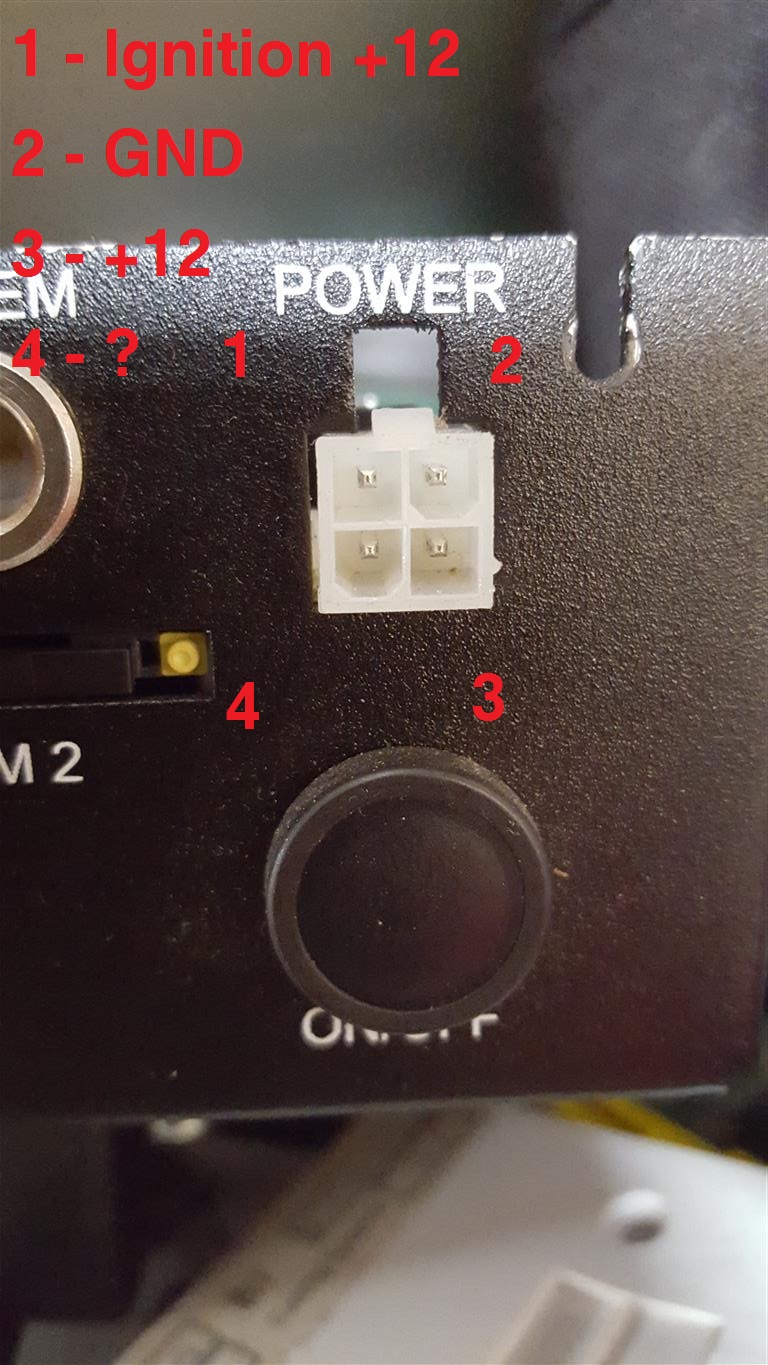
check that all rails are zero. any voltage on +5V or +%v Standby indicated a faulty USB device, many powered USB devices dont stop their power supplies tryin to power the bus. This isnt really a good idea and can cause boot and power/no post or not power faults. Evo Labs I’m looking at you here. Disconnect things until the voltage goes away, bin the responsible item (or meter pins 1/4 on the devices USB port to check then bin)

Meter all voltages while off with mains on. Check +5V USB/Stby is in tolerance, what you cann in tolerance is down to you but we will reject below 4.7. Make sure everything else is off. more than 200mV on any supply line while off is a reject. It points at control IC issues or a breakdown happening in the transformer. Voltage on the +5V rail may indicate the presence of USB devices that arent playing ball, see above.

Any issues at this point will cause power/no post, intermittant post or a dead machine (often with a faintly glowing power LED)

Check the +5 USB/Standby is clean with the scope. It *should* appear as a flat line. If it doesnt check your earths, expecially the meter earth lead. If you know how to read the display properly artifacts at 50Hz are normally pickup by the meter but could indicate a promary (main side) issue. ANy higher frequeny spikes above a few mV mean the PSU is failing and in particular the filter caps are probobly on the way out or its badly overloaded. Disconnect all but the mains lead and check again. If the spikes have gone work backwards plugging in things till they reappear. USB Novelties are the worst offendores here along with cheap hubs that may be overloaded.

Again any issues at this point will cause power/no post, intermittant post or a dead machine (often with a faintly glowing power LED) but a noisy %V rail can cause the machine to randomly lock up and in some cases turn itself on.

Noisy rails seem to be an issue with Evo Lab and clones, JueJye, earlier Enlight, and Acer’s own. The normal cause is low quality control, removal of filter components to reduce cost or falling victim to capacitor plague.

Power the machine up and work through the rails. Voltage first, then scope. Typical values are available at https://en.wikipedia.org/wiki/ATX but rule of thumb is there is 10% allowable tolerence on all rails. If you start seeing more than one rail badly out then you have an unhapy or overloaded PSU

The spikes on the rails should be as low as possible and they should be regular if at all. Excessive spikes (also called ripple) indcate a rail is way overloaded or its filters are failing. Excesive ripple will cause just about any random fault you can imagine from making ram seem faulty to cooking off grahics cards. High ripple is very very hard on the PC and will cause failures and can cause severe damage especially if the PSU fails.

Irregular spikes can indicate the PSU is close to its limit or something is going into protection somewhere. A few isnt much to worry abou but if these spikes co-incide with a lockup or crash they need to be linvestigated. You may find if you look closeley you’ll see the spikes on the monitor as flickers or faint bars. The latter typically points at filter caps on the board or graphics card having gone bad. A quick visual inspection will normaly find bulged or ruptured caps.

All of these issues can be present on a working PSU, if you dont go looking for them you’ll never find them and you can end up chasing your tail for hours. A simple substitution is always a good way to start a fault finding mission as PSU faults can show up anywhere.

An overloaded PSU will fail, and dont assume that because you are using 450W and you have a 500W PSU you are safe:
1) The PSU may not be capable of 450W, often lower end PSUs quote a peak power fugure that they can only breifly sustain.
2) Your 450W may ot be their 450W. Take all the rails listed on the side with currents and manualy convert them to watts EG 12V*16A = 192W. You will often find on lower end PSUs that the power doesnt add up when you sum them or that all the power is on +3.3V or +5V when its needed on +3.3V AND +12V
3) With the above info and looking at product data work out the power consumption on a PER RAIL basis, you may find quickly you dont have enough power
4) Give yourself headroom. 450W load on a 500W PSU is too close. You dont know how accurate those figures are and as systems age they can draw more power as caps dry out, fans start to stiffen up etc.

When you buy one:
1) Check the figures as per above. Add them up and look at where the power is.
2) If its split rail check continuity between the 12V lines with your meter and the PSU on the bench disconnected. You should fine two or more distinct 12V lines. Normally motherboard and Drive then GFX and ATX12V. If you get 0 ohms on all 12V lines then there is no split rail.
3) Look at the wiring. The wires should be substantial but not too thick. They certainly shouldnt be like bell or phone wire. Thinner wires result in more losses in voltage.

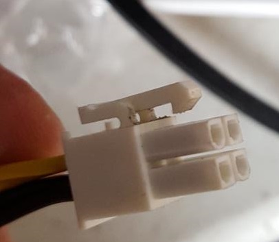
On the wiring you need to watch things here closley. Thinner wires means (as a rule) more resistance and this leads to something called Joule heating. Under a constant load this will reach a fixed point and wont get any worse. However as voltage at the device end drops more current is drawn, this causes a greater voltage drop and more Joule heating and things will either result in the device malfunctioning and shutting down OR catastrophic failure of the wire or device, either fire or a failure at a connector (this is what melts the SATA adaptors). If the device periodicaly and breifly demands high powers then this can cause voltage drop outs and other issues without the burning. Biggest culprit for this is hard drives on the end of a long chain of devices. This will reslut in the drive rebooting, data loss and eventually the drive failing.