Anyone who knows these cars and is trying to keep one on the road will sooner or later run into HEVAC problems. These seem to stem from the blend motors or the blower modules as a rule. As I have a spare one and a dead one on the car I decided to take the spare and totally overhaul it and try and see what actually fails on these as well as document how they work.
As with a number of modern cars these modules aren’t simply motors but contain some electronics too. Having dug deep in these Rover did some good work but were possibly constrained by what they had to work with, this seems to be the source of the issues.
Simpler cars simply use a multi position switch to feed a series of power resistors, these give you your different fan speeds. These resisters can and do fail, as do the switches and this can cause loss of speed settings, the whole fan and in some cases (Looking at you here Vauxhall) spontaneous combustion of the air box.
When you are looking at a climate control system you need to control the speed of the fan via a computer of some sort, switching relays and transistors can be done to use the resistor system but its simpler and more precise to use something called PWM. Here instead of a simple on/off signal we use a transistor as a switch to control the power to the motor. If we then switch the transistor quickly you can control the speed of the motor by how long the signal stays on. At a basic level you now have 255 speed settings vs 4 or 5 and the computer in the HEVAC can manage it electronically.
Most systems them mount the switching transistors on the motor assembly. Modern cars use the same system for engine fans and all sorts of other systems. You supply the fan with power and a switching signal and everything is normally cooled by the fan too. All the big heater resistors are redundant and controlling two fans for dual zone climate control as the P38 uses is much easier. It means there’s no heavy duty switching going on in the ECU (HEVAC Panel) so that can be smaller and integrated with the controls.
Now, The P38 system was advanced at the time but they did make some curious design decisions and were limited by the parts they had to use. A lot of P38 electrical gremlins come from the same source, bleeding edge design that was close to what was practical at the time.
So, lets tear into it…
Either blower comes out easy enough. The procedure is covered elsewhere and I won’t go into it. It does work a little easier on the V8 if you drop the Cruise relay and the ECU that’s with it off the bracket. You get more space.
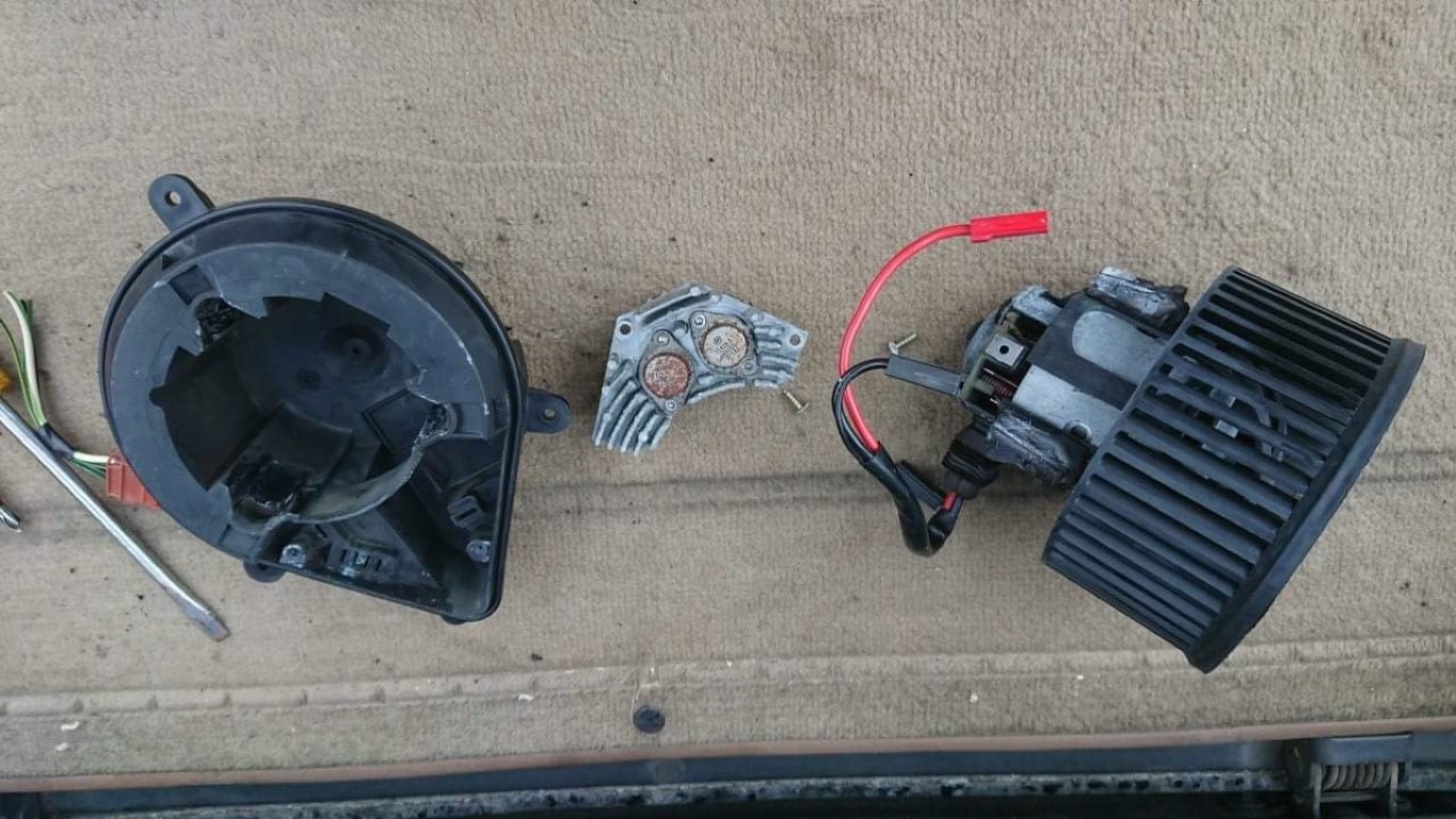
Once its out, pull the red and black motor connections from the electronics module. Looking at the side you’ll find three rectangular holes spaced equidistantly round the side. Push a flat screwdriver into each hole and gently pull the motor and fan assembly up out of the plastic. You’ll have to work around all three a few times but it will eventually prize out and you can guide the grommet and wiring through the plastic. Put the motor aside as we will look at this first, make sure the little rubber mounts do go astray. 3 screws hold the electronics to the plastic and the aluminum module can be withdrawn. You should have something like this now…
There are a few known issues. The most common is a simply dead unit, in which case you *could* likely swap just the electronics from a known good unit and snap it all back together. However I feel there may be other things at play here.
Another known issue is for the blower motors to torch the fuse box. The most commonly posited reason for this is blocked pollen filters, however with no air to circulate the load on the fan should be less, not more, so this explanation makes little sense. However stripping my unit I spotted something else, the motor was not free to move, well not as free as it should be. Powering the fan up from a bench power supply put the supply into protection at a current way above what I expected, Ah-Ha! So first job was to degunk, clean and lubricate the bearings. The top one is easy enough to do, the bottom one, less so. The motor cannot be stripped any further so its a case of the best you can do. Light machine oil was used on the bearings and some graphite grease to lube the brushes. The motor now not only span easier but drew significantly less current and was quieter. I would pin the fuse box burn outs on stiff motors before filters. As the whole lot comes apart easy enough this is a simple job to do “just in case”