So if you’ve not looked already, go look at Part 1.
At this point I’v discovered that my mainboard is screwed, it wont reboot cleanly and after a lot of playing the board is at fault. Its a brand new board so thats off to the suppliers. In the mean time more fiddling with the front panel.
An hour with a multimeter, pen and paper and I have the matrix mapped out, a bit of experimentation with LEDs and I’ve confirmed the wiring. Time to break out the breadboard.
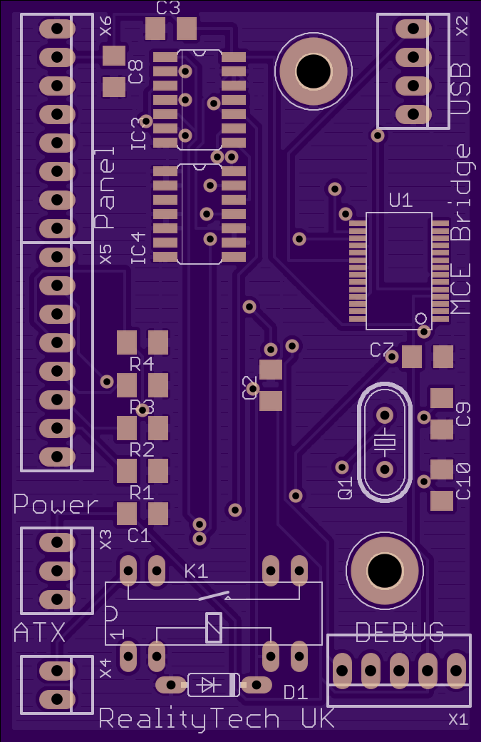
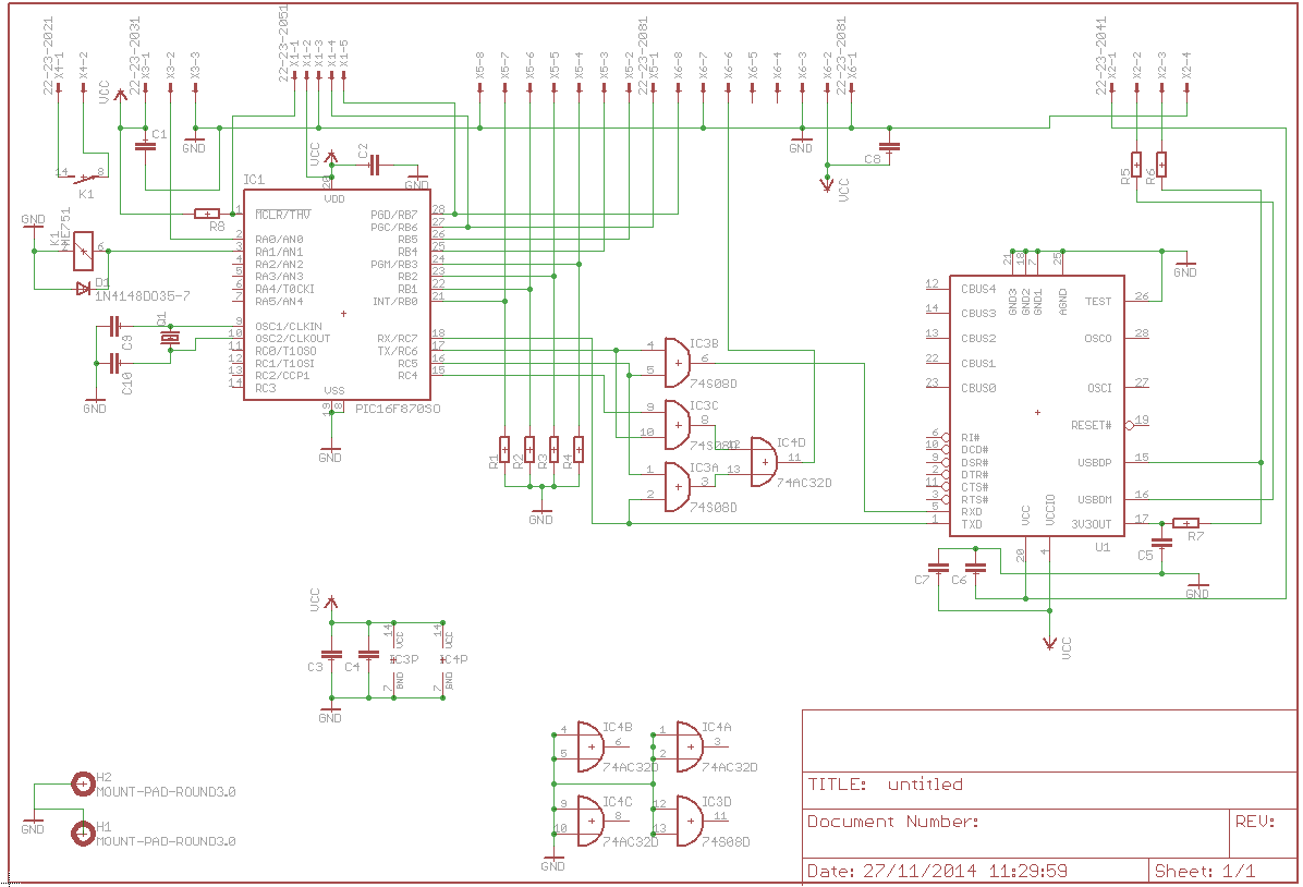
I chose to use a fairly high end PIC, the 16F870. Totally over the top for this BUT it leaves space for other things to go in there and importantly, unlike the 14 pin PICs I can use the ICD facility and I have at least two 8 bit ports. So the matrix is wired up to port b and we statr scanning. The code is pretty simple, it scans contantly in 1ms steps and looks for changes. If there is one the port is read yeilding the first 4 bits with the row being scanned and the lower 4 with the column thats active. Its crude but I just blast these out the serial port as raw scancodes rather than formatting. This does mean that if another keypad were used its just a software tweak in the driver to make it work (I may make the key vals customisable).
Now back to that power LED. Once the driver app runs it turns on the red standby LED and then wait for Media Centre to respond. When it does it switches the LED off and turns the green one on. Thats fine and dandy BUT if the machine is hibernating, if the driver crashes or something interrupts the boot you have no indication the box is doing anything. So we want that RED power LED on at power up and not needing to rely on the board booting. On top of that I’ve found the board doesnt always auto start AND the standby/power button needs handling.
First up I’ve thrown a handful of AND gates into the serial lines, this means I can now steer where the PIC’s serial goes. This means the first thing the PIC does is connect itself to the panel and turn that damn LED on. It then wires itself back to the serial from the PC and is hapy again at the same time making sure the inboud serial is shunted back to the front panel. The PIC can listen to this stream too but at the moment I have no use for that (It may get used for a watchdog) The driver now turns on both red and green LEDs giving an orange LED as the driver waits for MCE to start.
Next the power button and powering up the board….