Part 2 of this article.
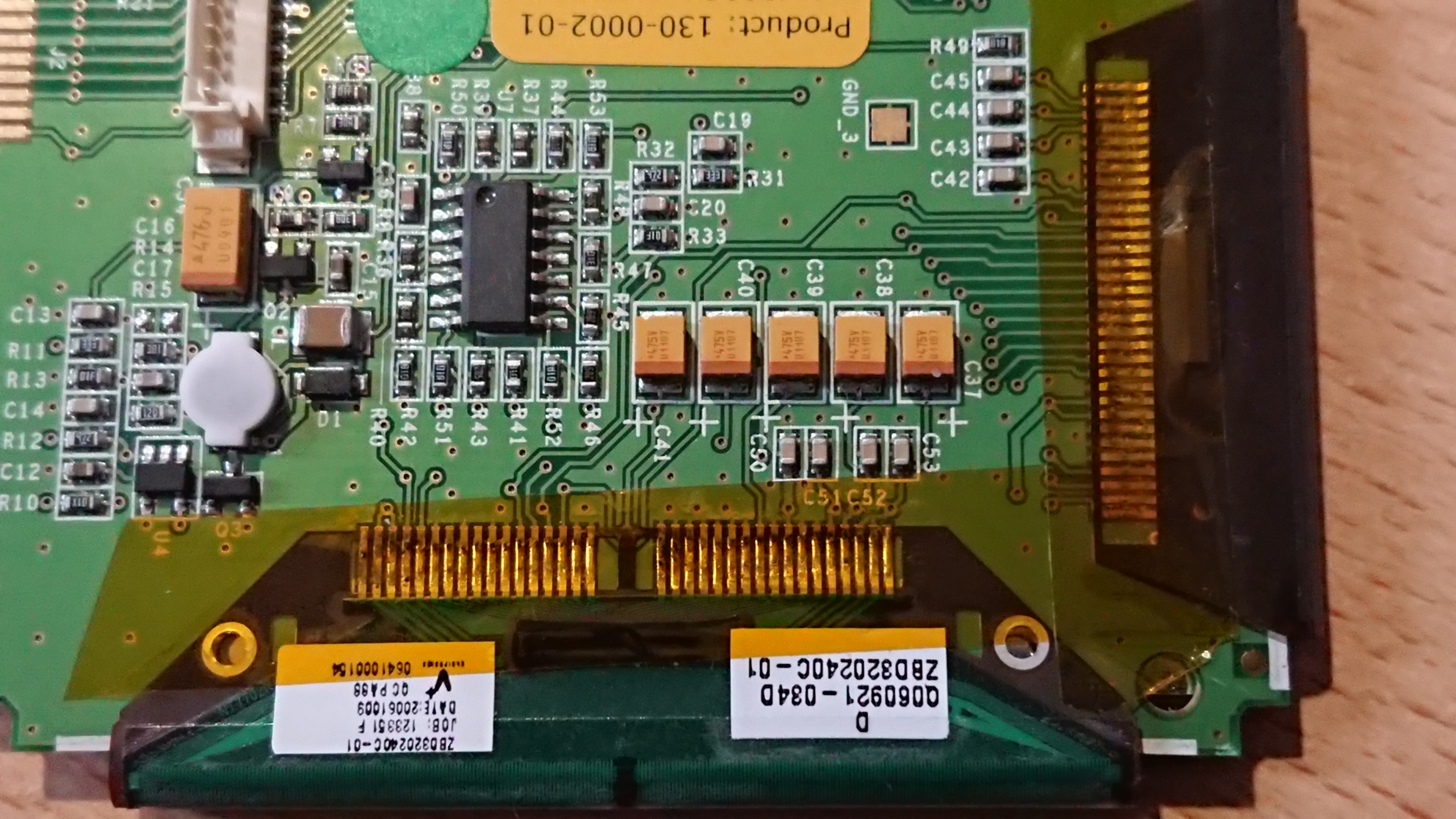
So popping the back of the case, just four screws, reveals this…
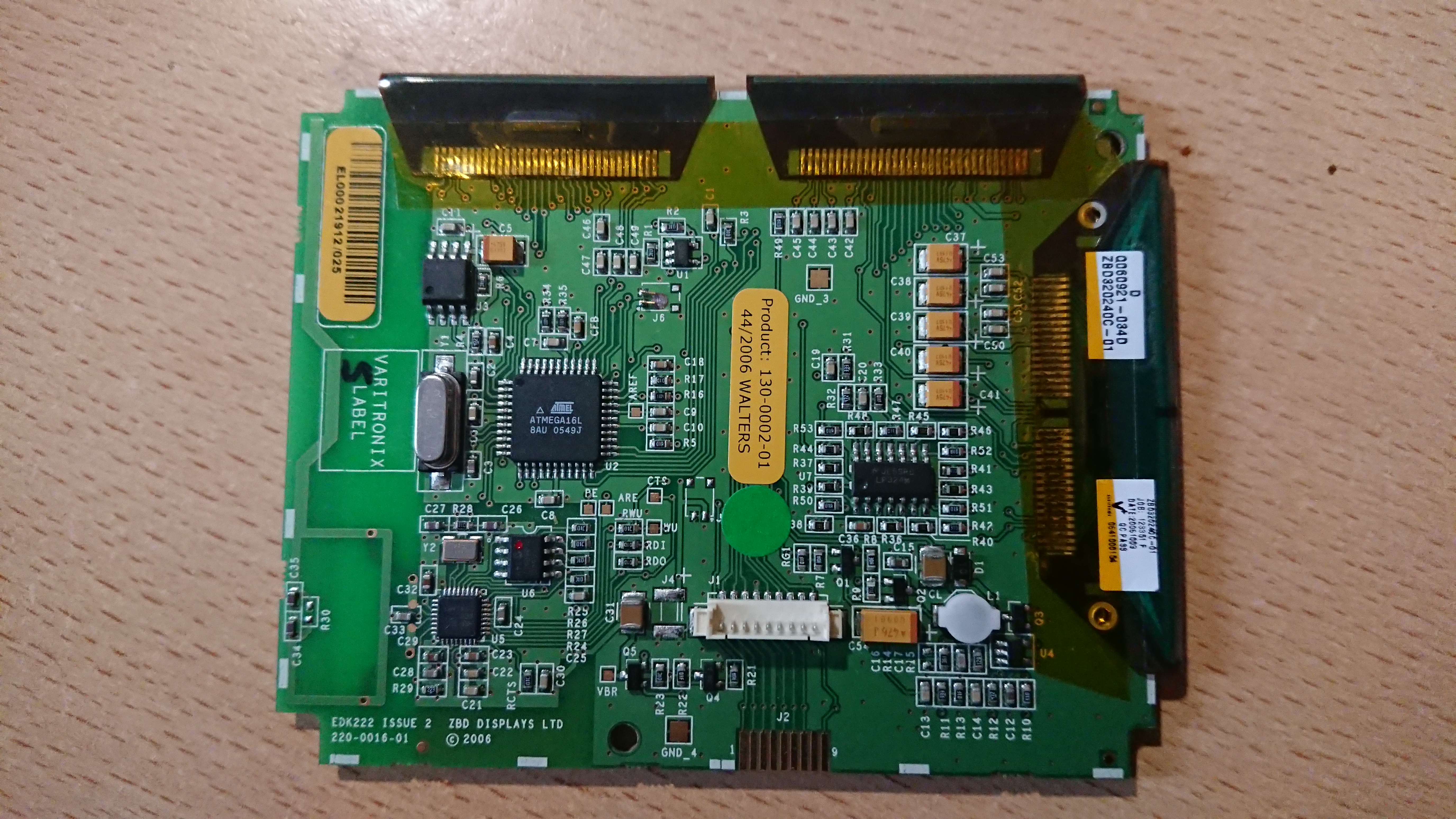
There really isnt much to the unit. On the pic of the front you can see a debug header at the bottom. this is duplicated twoce more on the reverse with a finer pitched connector AND a pin header. Quite why 3 copies were needed I don’t know but they are the exact same pinout. The front connection is a perfectly sensible size and pitch. This contains power, the uC’s serial and ICSP lines.
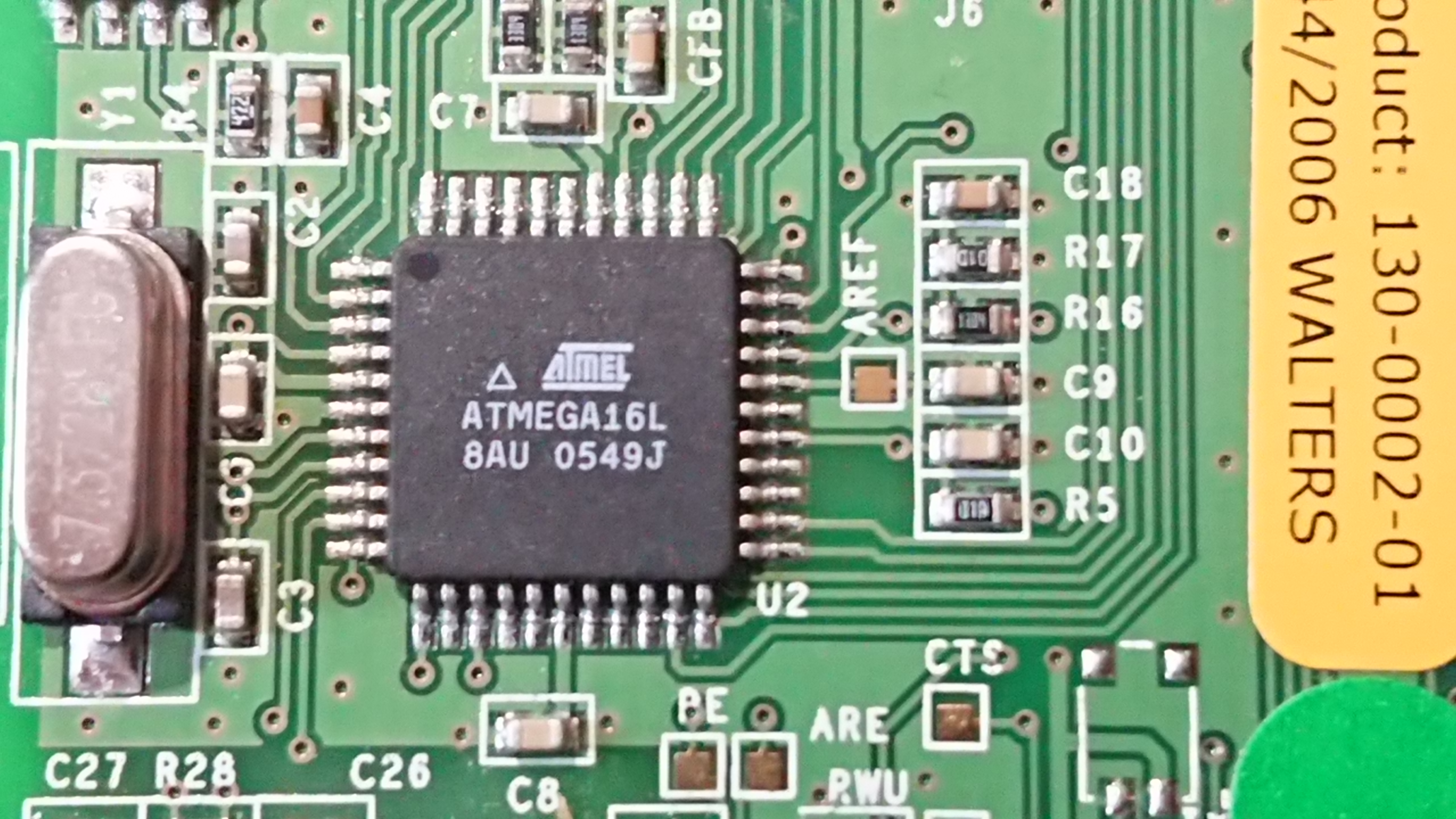
The uC is a well known and standard part that most will be familiar with from the Arduino range. That’s right, you *could* put the Arduino bootloader on here and if I can work out how to talk to the display it would effectiveley be possible to roll your own display controller. As we have no specs on the LCD itself this is non trivial. Immediateley above it and hooked to the SPI bus is 1Mbit of NOR flash. The crystal is 7.3728Mhz which may have been chosen to make things a bit easier on the UART, although there is no real need to do this.
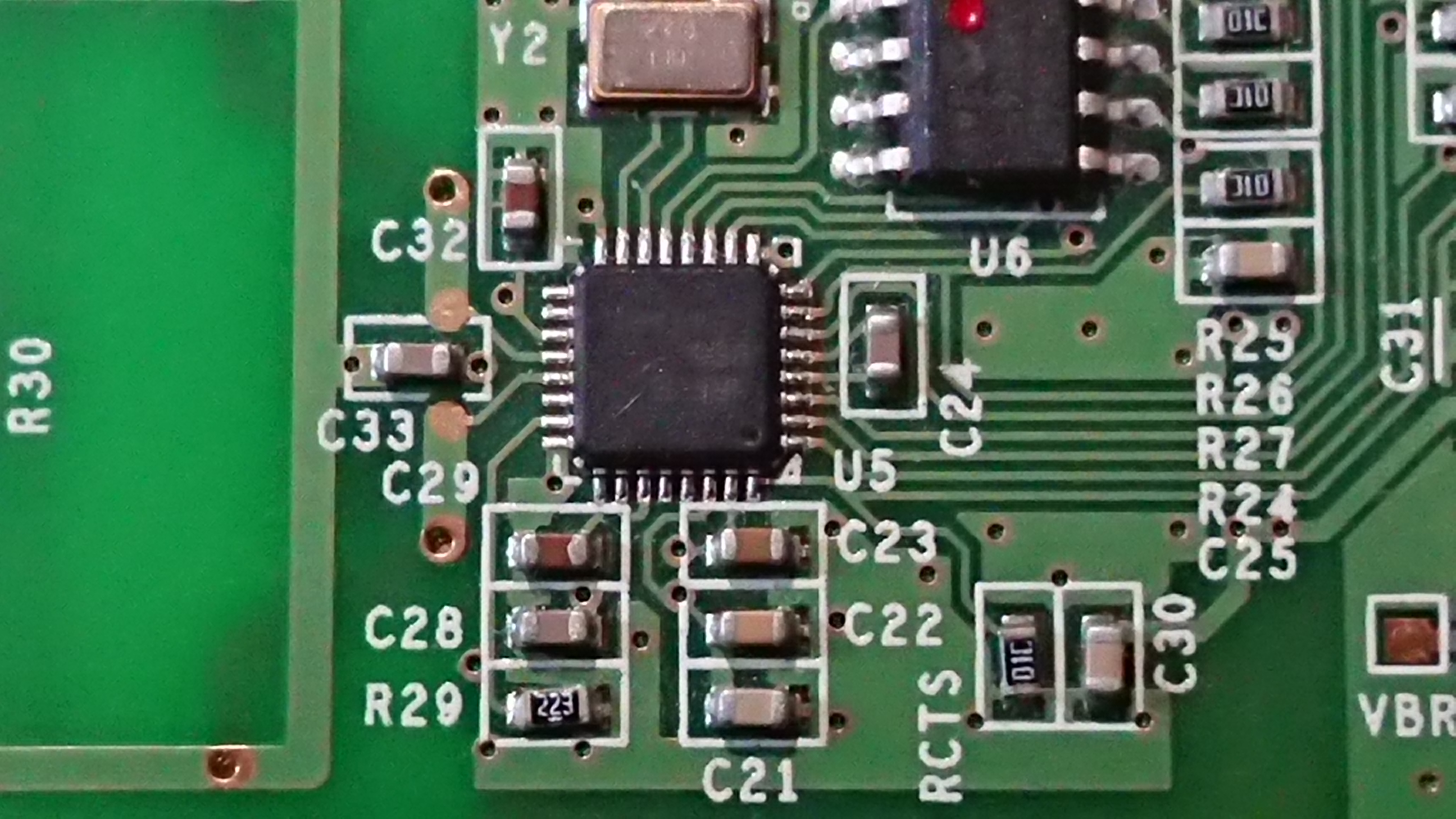
Below this is a Nordic Semi nRF9E5 RF SOC based on an 8051 core. Nordic Semi push this as a device for operation in the 433/868/915Mhz ISM bands. Given that only 433 is allowed in the UK (and europe I beleive) and looking at the antenna provided that’s where this will live. I can check this quickly enough with my SDR if I get time. however I’m not THAT interested in the radio at this time. These do answer back as the controller will complain if it sees no reply so these are full blown tranceivers and it may be possible to utilise them. The circuitry is quite well separated from the rest of the design suggestion it may have originated as a development board. RX, TX and CTS are labelled on the board, as are three other signals, BE, ARE and RWU. Quite what these are I don’t know however I would suspect there is at least one enable signal there.
This seems to be power supply territory. A bog standard LP324 op amp lives in the middle and then there are a good spattering of caps and an inductor here and what looks like a controller. This needs metering out when the display is doing something. The ribbon on this side seems mostly dedicaed to power with many pins linked. There is an IC buried in the flat flex here too so it’s not quite that simple. I would imagine this is power supplies and row select with the upper ribbons handling the columns.
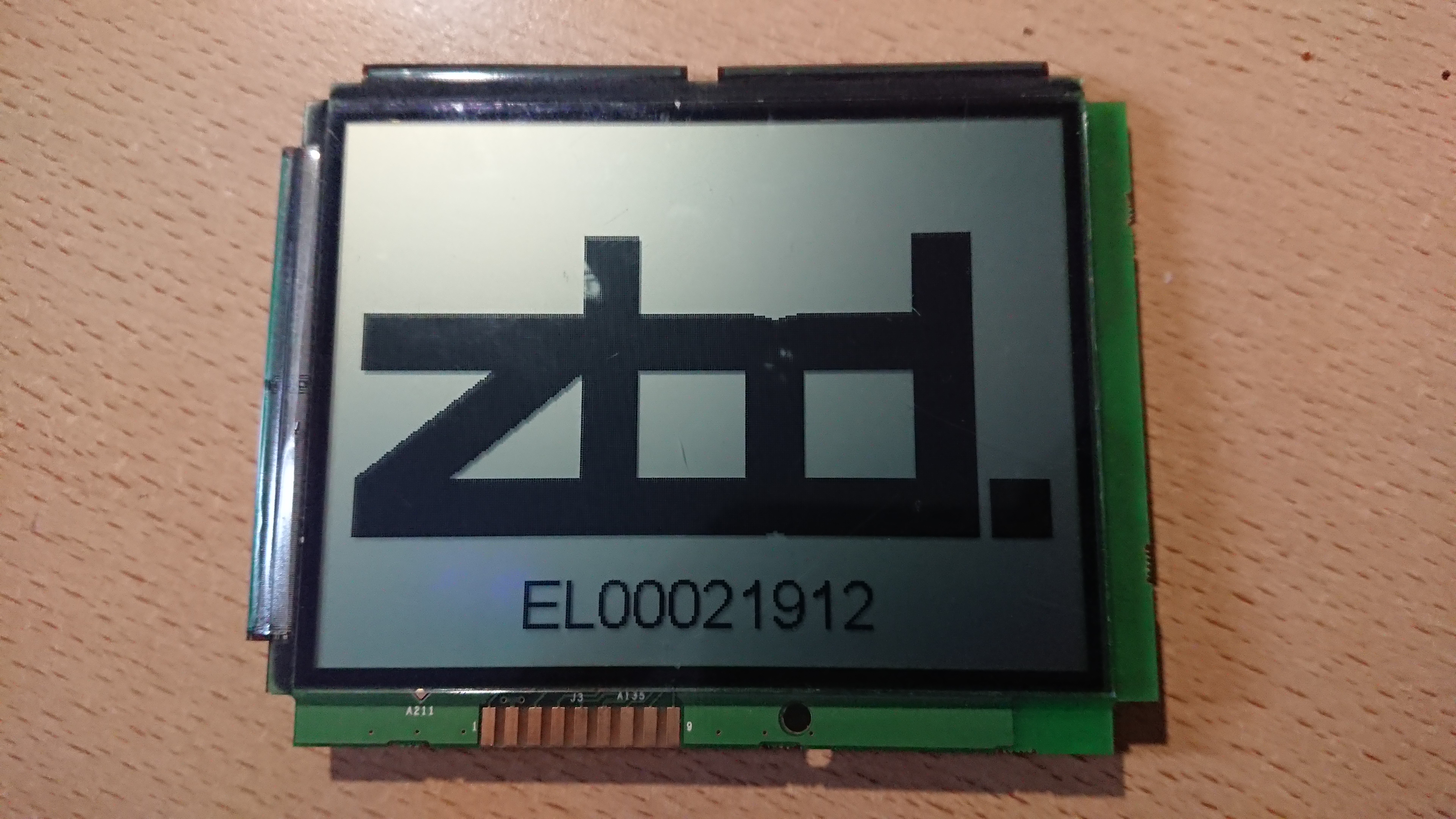
A close up of the display labels. The model number throws up a pdf : datasheet
This gives us something to go on, we have pin names and potentially the driver chips. We also have the display voltages, 3-5V for Logic and 15-20V for the display! Hence the power supplies.
The drivers seem to be referred to as ‘TAB’s and a quick look for the controllers listed not only gives the chip, but the flat flex layout in the datasheet. So for the top two tabs:
477731_1
And the side one:
393920_1
The top two cover 160 columns each and the side, 240 giving is a resolution of 320*240 which nmatches the image size the software asks for and the model of the display. Hopefully this provides what we need to drive the LCD itself, with out the need for constant refresh there is probobly less speed contraint on the scan time and indeed the scan does seem very slow when its refreshed. A quick check with a meter implies that the pinouts of the displays matches that of the tab. It also suggests that the NT7701s are cascaded as per the datasheet.
This gives us an 8 bit wide interface with 4 control lines and a clock. All of a sudden the idea of driving the display direct seems a little less daunting. With the large SPI EEPROM on board it should be possible to implement a char gen, although the limited RAM may be an issue. If we assume we use one byte per block of 8 pixels thats 320*240/8 = 9600 bytes or 10K of your 16K of RAM on the 16L8. If we are running as a display controller and nothing else this should be plenty. As we are only updating the display when it needs to change there is no need for double buffering etc.
A little update here: Part 2 1/2 – Life!
One thought on “ZBD EPOP Blade-C E-Ink Displays – Part 2”